RADAR SENSOR AIMING [MAZDA RADAR CRUISE CONTROL (MRCC) SYSTEM]
id0120g0012500
-
Warning
-
• If the radar sensor aiming adjustment is not completed, the Mazda Radar Cruise Control (MRCC) system, Smart Brake Support (SBS) system, and the Distance Recognition Support System (DRSS) will not operate normally which could lead to an unexpected accident. Therefore, when performing the following work, always perform the aiming adjustment so that the MRCC system, SBS system, and the DRSS operate normally.
-
― Vehicle control module (V/C-module) removal/installation, replacement
― Radar sensor, radar sensor bracket removal/installation, replacement
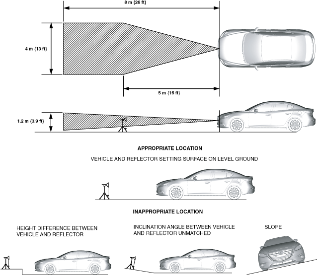
1. Park the vehicle on level ground.
-
Caution
-
• If the vehicle and reflector are set at different heights or different angles, accurate adjustment cannot be performed.
• Level ground conditions must be within 1 degree for the front and back, and right and left.
• Perform the work in an area where 8 m {26 ft} or more of space from the vehicle front and 4 m {13 ft} or more of width are available.
• Perform the aiming adjustment in a place where there is no obstruction up to approx. 1.2 m {3.9 ft} from the road surface at approx. 8 m {26 ft} from vehicle front.
• Remove cargo from the cabin and trunk compartment so that the vehicle is in an unloaded condition.
• Adjust the tire pressure of each tire to the specified value.
• Do not let foreign material (metal, plastic material) get into the aiming implementation area to prevent radio wave interference.
• Do not move or shake the vehicle during aiming adjustment (such as riding in or opening a door).
• Remove dust or dirt from the radiator grille ornament.
• Do not turn the power off during the aiming adjustment.
• The voltage supplied to the radar sensor must be 9.5—15.5 V.
• The aiming adjustment must be performed under approx. -30—60 °C {-22—140 °F} conditions.
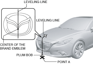
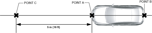
2. Adjust the SST (plum-bob) so that it is aligned with the center of the brand emblem, determine the center position at the front of the vehicle, and mark the center position (point A) on the floor surface.
-
Note
-
• The center of the brand emblem indicates the center position of the vehicle.
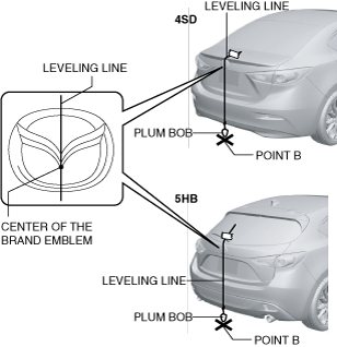
3. Adjust the SST (plum-bob) so that it is aligned with the center of the brand emblem, determine the center position at the rear of the vehicle, and mark the center position (point B) on the floor surface.
-
Note
-
• The center of the brand emblem indicates the center position of the vehicle.
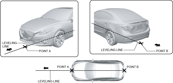
4. Secure the end of the leveling line over point B.
-
Note
-
• Use a commercially-available leveling line.
5. Pull the unsecured end of the leveling line over the vehicle and to the front and adjust it so that it passes over point A.
6. Mark the line (position A) at the point 5 m {16 ft} from point A and in the direction forward of the vehicle.
-
Note
-
• If the leveling line is secured at the vehicle front center point (point A), the leveling line may deviate. Therefore, secure the leveling line in the order of point B, point C, and point A.
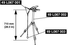
7. Install the SST (reflector and plum bob) to the SST (tripod).
8. Adjust so that the height of the SST (reflector) from the floor surface is 710 mm {28.0 in}.
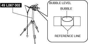
9. Level the SST (reflector) by adjusting the leveling bubble on the SST (tripod) so that it is centered on the bubble reference line.
-
Note
-
• A commercially-available tripod equipped with a level can be substituted for the SST (stand).
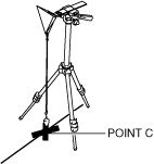
10. Set the SST (stand) with the SST (plum-bob) and the marking aligned.
-
Note
-
• Visually verify that the reflection surface of the reflector faces the vehicle.
11. Visually inspect the surfaces of the radar sensor and the radiator grille ornament for the following:
-
• Dirt is adhering to radar sensor surface
• Dirt is adhering to radiator grille ornament surface
• Foreign material (reflective object) is adhering to radar sensor
• Foreign material (reflective object) is adhering to radiator grille ornament surface
12. Connect the M-MDS to the DLC-2.
-
Caution
-
• If the engine is started, the aiming may not be performed correctly due to oscillation. Perform the aiming with the engine stopped.
13. After the vehicle is identified, select the following items from the initialization screen of the M-MDS.
- (1) Select "Electrical".
-
- (2) Select "SBS/MRCC".
-
- (3) Select "Radar Aiming".
-
14. Perform the aiming adjustment following the instructions on the screen.
15. If "Aiming has been unsuccessful." Is displayed on the screen, repair according to the error code in the following chart.
-
• If verification and repair are completed, perform the aiming adjustment again.
|
Error code
|
Item
|
Possible cause
|
Inspection item (s)
|
|
Code 1
|
Improper target position
|
• SST (reflector) installation mistake
• Marking setting mistake
• Improper installation of radar sensor
• Radar sensor and vehicle control module (V/C-module) malfunction
|
• SST (reflector) installation condition
• Marking setting condition (SST string)
• Radar sensor installation condition and installation part condition
• Applicable DTC troubleshooting
|
|
Code 2
|
Improper target angle
|
• SST (reflector) installation mistake
• Marking setting mistake
• Improper installation of radar sensor
• Radar sensor and vehicle control module (V/C-module) malfunction
|
• SST (reflector) installation condition
• Marking setting condition (SST string)
• Radar sensor installation condition and installation part condition
• Applicable DTC troubleshooting
|
|
Code 3
|
Multiple targets
|
• There is reflective object on area around SST (reflector) which could become a possible target
• Radar sensor and vehicle control module (V/C-module) malfunction
|
• Remove reflective object on area around SST (reflector) which could become a possible target
• Applicable DTC troubleshooting
|
|
Code 4
|
Target moves
|
• SST (reflector) moves (within radar sensor reception range) during aiming
• Radar sensor and vehicle control module (V/C-module) malfunction
|
• SST (reflector) installation condition
• Applicable DTC troubleshooting
|
|
Code 5
|
No target
|
• Voltage supplied to radar sensor is out of specification
• Aiming performed under out-of-specification temperature
• Dirt is adhering to radar sensor or radiator grille ornament
• Dirt is adhering to SST (reflector)
• SST (reflector) is deformed
• SST (reflector) does not exist (within radar sensor reception range) during aiming
• Radar sensor and vehicle control module (V/C-module) malfunction
|
• Radar sensor supply voltage inspection (approx. 9.5—15.5 V)
• Ambient temperature verification (approx. -30—60 °C {-22—140 °F})
• Remove dirt from radar senor or radiator grille ornament surface
• Remove dirt from SST (reflector)
• Replace SST (reflector)
• SST (reflector) installation condition
• Applicable DTC troubleshooting
|
|
Code 7
|
Vehicle condition malfunction
|
• Vehicle moves during aiming (vehicle door opening/closing, getting on vehicle) (change in wheel speed)
• Radar sensor and vehicle control module (V/C-module) malfunction
|
• Verification of selector lever position (in P position) (ATX)
• Verification of shift lever position (in neutral position) (MTX)
|
|
Code 8
|
Recording fails
|
• Communication error between radar sensor and vehicle control module (V/C-module)
• Radar sensor and vehicle control module (V/C-module) malfunction
|
• Applicable DTC troubleshooting
|