|
1
|
VERIFY FREEZE FRAME DATA (MODE 2)/SNAPSHOT DATA AND DIAGNOSTIC MONITORING TEST RESULTS HAVE BEEN RECORDED
• Have the FREEZE FRAME DATA (Mode 2)/snapshot data and DIAGNOSTIC MONITORING TEST RESULTS (A/F sensor, HO2S related) been recorded?
|
Yes
|
Go to the next step.
|
|
No
|
Record the FREEZE FRAME DATA (Mode 2)/snapshot data and DIAGNOSTIC MONITORING TEST RESULTS on repair order, then go to the next step.
|
|
2
|
VERIFY RELATED SERVICE INFORMATION AVAILABILITY
• Verify related Service Information availability.
• Is any related Service Information available?
|
Yes
|
Perform repair or diagnosis according to the available Service Information.
• If the vehicle is not repaired, go to the next step.
|
|
No
|
Go to the next step.
|
|
3
|
VERIFY RELATED PENDING CODE AND STORED DTC
-
Note
-
• If the fuel monitor DTC, DTC P0132:00 is retrieved, ignore it until P0140:00 is fixed.
• Switch the ignition off, then ON (engine off).
• Verify the related PENDING CODE and stored DTCs using the M-MDS.
• Are any other DTCs present?
|
Yes
|
Go to the applicable DTC inspection.
|
|
No
|
Go to the next step.
|
|
4
|
INSPECT INSTALLATION OF HO2S
• Inspect if the HO2S is loosely installed.
• Is the HO2S installed securely?
|
Yes
|
Go to the next step.
|
|
No
|
Retighten the HO2S, then go to Step 14.
|
|
5
|
INSPECT GAS LEAKAGE FROM EXHAUST SYSTEM
• Visually inspect if there is any gas leakage between the exhaust manifold and HO2S.
• Is there any leakage?
|
Yes
|
Repair or replace the malfunctioning part according to the inspection results, then go to Step 14.
|
|
No
|
Go to the next step.
|
|
6
|
INSPECT HO2S CONNECTOR CONDITION
• Switch the ignition off.
• Disconnect the HO2S connector.
• Inspect for poor connection (such as damaged/pulled-out pins, corrosion).
• Is there any malfunction?
|
Yes
|
Repair or replace the connector or terminals, then go to Step 14.
|
|
No
|
Go to the next step.
|
|
7
|
INSPECT HO2S HEATER
• Inspect the HO2S heater.
• Is there any malfunction?
|
Yes
|
Replace the HO2S, then go to Step 14.
|
|
No
|
Go to the next step.
|
|
8
|
INSPECT PCM CONNECTOR CONDITION
• Disconnect the PCM connector.
• Inspect for poor connection (such as damaged/pulled-out pins, corrosion).
• Is there any malfunction?
|
Yes
|
Repair or replace the connector or terminals, then go to Step 14.
|
|
No
|
Go to the next step.
|
|
9
|
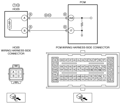
INSPECT HO2S SIGNAL CIRCUIT FOR SHORT TO GROUND
• Verify that the HO2S and PCM connectors are disconnected.
• Inspect for continuity between HO2S terminal A (wiring harness-side) and body ground.
• Is there continuity?
|
Yes
|
Refer to the wiring diagram and verify whether or not there is a common connector between HO2S terminal A and PCM terminal 1AB.
If there is a common connector:
• Determine the malfunctioning part by inspecting the common connector and the terminal for corrosion, damage, or pin disconnection, and the common wiring harness for a short to ground.
• Repair or replace the malfunctioning part.
If there is no common connector:
• Repair or replace the wiring harness which has a short to ground.
Go to Step 14.
|
|
No
|
Go to the next step.
|
|
10
|
INSPECT HO2S SIGNAL CIRCUIT FOR OPEN CIRCUIT
• Verify that the HO2S and PCM connectors are disconnected.
• Inspect for continuity between HO2S terminal A (wiring harness-side) and PCM terminal 1AB (wiring harness-side).
• Is there continuity?
|
Yes
|
Go to the next step.
|
|
No
|
Refer to the wiring diagram and verify whether or not there is a common connector between HO2S terminal A and PCM terminal 1AB.
If there is a common connector:
• Determine the malfunctioning part by inspecting the common connector and the terminal for corrosion, damage, or pin disconnection, and the common wiring harness for an open circuit.
• Repair or replace the malfunctioning part.
If there is no common connector:
• Repair or replace the wiring harness which has an open circuit.
Go to Step 14.
|
|
11
|
INSPECT SEALING OF ENGINE COOLANT PASSAGE
• Perform the “ENGINE COOLANT LEAKAGE INSPECTION”.
• Is there any malfunction?
|
Yes
|
Repair or replace the malfunctioning part according to the inspection results, then go to Step 14.
|
|
No
|
Go to the next step.
|
|
12
|
INSPECT ENGINE COMPRESSION
• Inspect the engine compression.
• Is there any malfunction?
|
Yes
|
Repair or replace the malfunctioning parts according to the inspection results, then go to Step 14.
|
|
No
|
Go to the next step.
|
|
13
|
INSPECT HO2S
• Reconnect all disconnected connectors.
• Is there any malfunction?
|
Yes
|
Replace the HO2S, then go to the next step.
|
|
No
|
Go to the next step.
|
|
14
|
VERIFY DTC TROUBLESHOOTING COMPLETED
• Always reconnect all disconnected connectors.
• Clear the DTC from the PCM memory using the M-MDS.
• Perform the Drive Mode 03 (A/F sensor heater, HO2S heater, A/F sensor, HO2S and TWC Repair Verification Drive Mode).
• Is the PENDING CODE for this DTC present?
|
Yes
|
Repeat the inspection from Step 1.
• If the malfunction recurs, replace the PCM.
Go to the next step.
|
|
No
|
Go to the next step.
|
|
15
|
VERIFY AFTER REPAIR PROCEDURE
• Perform the “AFTER REPAIR PROCEDURE”.
• Are any DTCs present?
|
Yes
|
Go to the applicable DTC inspection.
|
|
No
|
DTC troubleshooting completed.
|