|
1
|
RECORD VEHICLE STATUS AT TIME OF DTC DETECTION TO UTILIZE WITH REPEATABILITY VERIFICATION
-
Note
-
• Recording can be facilitated using the screen capture function of the PC.
• Record the FREEZE FRAME DATA/snapshot data on the repair order.
|
—
|
Go to the next step.
|
|
2
|
VERIFY RELATED SERVICE INFORMATION AVAILABILITY
• Verify related Service Information availability.
• Is any related Service Information available?
|
Yes
|
Perform repair or diagnosis according to the available Service Information.
• If the vehicle is not repaired, go to the next step.
|
|
No
|
Go to the next step.
|
|
3
|
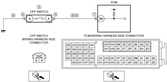
INSPECT CPP SWITCH CONNECTOR CONDITION
• Switch the ignition off.
• Disconnect the CPP switch connector.
• Inspect for poor connection (such as damaged/pulled-out pins, corrosion).
• Is there any malfunction?
|
Yes
|
Repair or replace the connector and/or terminals, then go to Step 11.
|
|
No
|
Go to the next step.
|
|
4
|
VERIFY IF MALFUNCTION OCCURS DUE TO FOREIGN OBJECT LODGED BETWEEN CPP SWITCH PLUNGER AND CLUTCH PEDAL CONTACT SURFACE
• Visually verify the area between the CPP switch plunger and clutch pedal contact surface.
• Is there a lodged foreign object?
|
Yes
|
Remove the foreign object, then go to the next step.
|
|
No
|
Go to the next step.
|
|
5
|
INSPECT CPP SWITCH
• Inspect the CPP switch.
• Is there any malfunction?
|
Yes
|
Replace the CPP switch, then go to Step 11.
|
|
No
|
Go to the next step.
|
|
6
|
INSPECT CPP SWITCH GROUND CIRCUIT FOR OPEN CIRCUIT
• Verify that the CPP switch connector is disconnected.
• Inspect for continuity between CPP switch terminal B (wiring harness-side) and body ground.
• Is there continuity?
|
Yes
|
Go to the next step.
|
|
No
|
Refer to the wiring diagram and verify whether or not there is a common connector between CPP switch terminal B and body ground.
If there is a common connector:
• Determine the malfunctioning part by inspecting the common connector and the terminal for corrosion, damage, or pin disconnection, and the common wiring harness for an open circuit.
• Repair or replace the malfunctioning part.
If there is no common connector:
• Inspect for the following:
-
― Open circuit between CPP switch and body ground
― Loose or lifting ground point
-
• Repair or replace the malfunctioning part.
Go to Step 11.
|
|
7
|
INSPECT PCM CONNECTOR CONDITION
• Disconnect the PCM connector.
• Inspect for poor connection (such as damaged/pulled-out pins, corrosion).
• Is there any malfunction?
|
Yes
|
Repair or replace the connector and/or terminals, then go to Step 11.
|
|
No
|
Go to the next step.
|
|
8
|
INSPECT CPP SWITCH SIGNAL CIRCUIT FOR SHORT TO GROUND
• Verify that the CPP switch and PCM connectors are disconnected.
• Inspect for continuity between CPP switch terminal A (wiring harness-side) and body ground.
• Is there continuity?
|
Yes
|
Refer to the wiring diagram and verify whether or not there is a common connector between CPP switch terminal A and PCM terminal 2M.
If there is a common connector:
• Determine the malfunctioning part by inspecting the common connector and the terminal for corrosion, damage, or pin disconnection, and the common wiring harness for a short to ground.
• Repair or replace the malfunctioning part.
If there is no common connector:
• Repair or replace the wiring harness which has a short to ground.
Go to Step 11.
|
|
No
|
Go to the next step.
|
|
9
|
INSPECT CPP SWITCH SIGNAL CIRCUIT FOR OPEN CIRCUIT
• Verify that the CPP switch and PCM connectors are disconnected.
• Inspect for continuity between CPP switch terminal A (wiring harness-side) and PCM terminal 2M (wiring harness-side).
• Is there continuity?
|
Yes
|
Go to the next step.
|
|
No
|
Refer to the wiring diagram and verify whether or not there is a common connector between CPP switch terminal A and PCM terminal 2M.
If there is a common connector:
• Determine the malfunctioning part by inspecting the common connector and the terminal for corrosion, damage, or pin disconnection, and the common wiring harness for an open circuit.
• Repair or replace the malfunctioning part.
If there is no common connector:
• Repair or replace the wiring harness which has an open circuit.
Go to Step 11.
|
|
10
|
VERIFY THAT THERE IS NO PROBLEM WITH CUSTOMER CLUTCH PEDAL OPERATION
• Is the clutch pedal depressed after operating the shift lever during a traffic jam?
|
Yes
|
Explain to the customer that it is necessary to remove the foot from the clutch pedal completely after operating the shift lever.
Go to the next step.
|
|
No
|
Go to the next step.
|
|
11
|
VERIFY DTC TROUBLESHOOTING COMPLETED
• Always reconnect all disconnected connectors.
• Clear the DTC from the PCM memory using the M-MDS.
• Access the CPP PID using the M-MDS.
• Verify that the monitor value changes each time the clutch pedal is depressed.
• Perform the Pending Trouble Code Access Procedure.
• Is the PENDING CODE for this DTC present?
|
Yes
|
Repeat the inspection from Step 1.
• If the malfunction recurs, replace the PCM.
Go to the next step.
|
|
No
|
Go to the next step.
|
|
12
|
VERIFY AFTER REPAIR PROCEDURE
• Perform the “AFTER REPAIR PROCEDURE”.
• Are any DTCs present?
|
Yes
|
Go to the applicable DTC inspection.
|
|
No
|
DTC troubleshooting completed.
|