 |
am3zzw00037242
DTC P250A:00 [SKYACTIV-D 1.5]
id0102q2787200
Details On DTCs
|
DESCRIPTION |
Engine oil level signal: engine oil level sensor malfunction |
|
|---|---|---|
|
DETECTION CONDITION
|
Determination conditions
|
• PCM receives error signal from engine oil level sensor.
|
|
Preconditions
|
• Battery voltage: 10—16 V
• The following DTC is not detected:
• Low-G (XY) sensor signal is normal
|
|
|
Drive cycle
|
• 1
|
|
|
Self test type
|
• CMDTC self test
|
|
|
Sensor used
|
• Engine oil level sensor
• Engine oil temperature sensor
• Low-G (XY) sensor
|
|
|
FAIL-SAFE FUNCTION
|
• Not applicable
|
|
|
VEHICLE STATUS WHEN DTCs ARE OUTPUT
|
• Illuminates master warning light
|
|
|
POSSIBLE CAUSE
|
• Excessive engine oil level (oil level exceeds measurable upper limit range of engine oil level sensor)
• Engine oil level sensor malfunction
• Erratic signal to PCM
• PCM malfunction
|
|
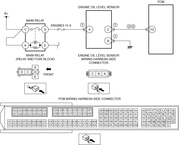
System Wiring Diagram
am3zzw00037242
|
Function Explanation (DTC Detection Outline)
Repeatability Verification Procedure
PID Item/Simulation Item Used In Diagnosis
PID/DATA monitor item table
|
Item
|
Definition
|
Unit
|
Condition/Specification
|
|
EOL
|
Engine oil level
|
mm, in
|
• Displays the engine oil level.
|
|
EOT
|
Engine oil temperature
|
°C, °F
|
• Displays engine oil temperature
|
Function Inspection Using M-MDS
|
STEP |
INSPECTION |
ACTION |
|
|---|---|---|---|
|
1
|
PURPOSE: RECORD VEHICLE STATUS AT TIME OF DTC DETECTION TO UTILIZE WITH REPEATABILITY VERIFICATION
• Record the snapshot data on the repair order.
|
—
|
Go to the next step.
|
|
2
|
PURPOSE: VERIFY RELATED SERVICE INFORMATION AVAILABILITY
• Verify related Service Information availability.
• Is any related Service Information available?
|
Yes
|
Perform repair or diagnosis according to the available Service Information.
• If the vehicle is not repaired, go to the next step.
|
|
No
|
Go to the next step.
|
||
|
3
|
PURPOSE: IDENTIFY TRIGGER DTC FOR FREEZE FRAME DATA
• Is the DTC P250A:00 on FREEZE FRAME DATA?
|
Yes
|
Go to the next step.
|
|
No
|
Go to the troubleshooting procedure for DTC on FREEZE FRAME DATA.
(See DTC TABLE [SKYACTIV-D 1.5].)
|
||
|
4
|
PURPOSE: VERIFY IF DIAGNOSTIC RESULT IS AFFECTED BY OTHER RELATED DTCs OCCURRING
• Switch the ignition off, then ON (engine off).
• Perform the Pending Trouble Code Access Procedure and DTC Reading Procedure.
• Is the other PENDING CODE/DTC also present?
|
Yes
|
Go to the applicable DTC inspection.
(See DTC TABLE [SKYACTIV-D 1.5].)
|
|
No
|
Go to the next step.
|
||
|
5
|
PURPOSE: DETERMINE IF CAUSE IS ERROR SIGNAL FROM ENGINE OIL LEVEL SENSOR
• Clear the DTC from the PCM memory using the M-MDS.
• Access the following PID using the M-MDS:
PCM:
• Start the engine and warm up until the value of PID EOT is 60 °C {140 °F} or more.
• After engine warm-up, perform the DTC inspection for the PCM.
• Is the same DTC present?
|
Yes
|
Go to the troubleshooting procedure to perform the procedure from Step 1.
|
|
No
|
Go to the next step.
|
||
|
6
|
PURPOSE: VERIFY ACTUAL ENGINE OIL LEVEL
• Switch the ignition ON (engine off) and leave for 5 min.
• Pull out the dipstick.
• Verify if the engine oil level is 8 mm {0.3 in} or more from the upper limit position of the dipstick.
• Is it 8 mm {0.3 in} or more?
|
Yes
|
Go to Step 8.
|
|
No
|
Go to the next step.
|
||
|
7
|
PURPOSE: VERIFY IF CAUSE IS ENGINE OIL LEVEL SENSOR STICKING MALFUNCTION
• Access the following PID using the M-MDS:
PCM:
• Start the engine while verifying the monitor value with the ignition switched ON (engine off).
• Leave for 30 s or more.
• Does the monitor value decrease by 7 mm {0.3 in} or more compared to the value with the ignition switched ON (engine off)?
|
Yes
|
A temporary malfunction can be considered.
• Perform the [ACTION FOR NON-REPEATABLE MALFUNCTIONS].
(See FOREWORD [SKYACTIV-D 1.5].)
|
|
No
|
Go to the troubleshooting procedure to perform the procedure from Step 1.
|
||
|
8
|
PURPOSE: VERIFY IF CAUSE IS EXCESSIVE ENGINE OIL LEVEL
• Switch the ignition ON (engine off).
• Access the following PID using the M-MDS:
PCM:
• Verify the monitor value with the ignition switched ON (engine off).
• Is the monitor value 95.8 mm {3.77 in} or more?
|
Yes
|
Adjust the engine oil level near the middle of the upper and lower limit position on the dipstick.
Go to the next step.
|
|
No
|
Go to the troubleshooting procedure to perform the procedure from Step 1.
|
||
|
9
|
PURPOSE: VERIFY IF CAUSE IS ENGINE OIL LEVEL SENSOR STICKING MALFUNCTION
• Access the following PID using the M-MDS:
PCM:
• Start the engine while verifying the monitor value with the ignition switched ON (engine off).
• Leave for 30 s or more.
• Does the monitor value decrease by 7 mm {0.3 in} or more compared to the value with the ignition switched ON (engine off)?
|
Yes
|
The cause is an excessive engine oil amount exceeding the measurable range of the engine oil level sensor. Replace the engine oil because there is the possibility that the engine oil is diluted.
Go to the troubleshooting procedure to perform the procedure from Step 4.
|
|
No
|
Go to the troubleshooting procedure to perform the procedure from Step 1.
|
||
Troubleshooting Diagnostic Procedure
|
STEP |
INSPECTION |
ACTION |
|
|---|---|---|---|
|
1
|
PURPOSE: INSPECT ENGINE OIL LEVEL SENSOR CONNECTOR CONDITION
• Switch the ignition off.
• Disconnect the engine oil level sensor connector.
• Inspect for poor connection (such as damaged/pulled-out pins, corrosion).
• Is there any malfunction?
|
Yes
|
Go to the next step.
|
|
No
|
Repair or replace the connector and/or terminals, then go to Step 4.
|
||
|
2
|
PURPOSE: INSPECT ENGINE OIL LEVEL SENSOR CONTROL CIRCUIT FOR SHORT TO GROUND
• Disconnect the PCM connector.
• Verify that the engine oil level sensor and PCM connectors are disconnected.
• Inspect for continuity between engine oil level sensor terminal C (wiring harness-side) and body ground.
• Is there continuity?
|
Yes
|
Refer to the wiring diagram and verify whether or not there is a common connector between engine oil level sensor terminal C and PCM terminal 1Q.
If there is a common connector:
• Determine the malfunctioning part by inspecting the common connector and the terminal for corrosion, damage, or pin disconnection, and the common wiring harness for a short to ground.
• Repair or replace the malfunctioning part.
If there is no common connector:
• Repair or replace the wiring harness which has a short to ground.
Go to Step 4.
|
|
No
|
Go to the next step.
|
||
|
3
|
INSPECT ENGINE OIL LEVEL SENSOR CIRCUIT FOR OPEN CIRCUIT
• Verify that the engine oil level sensor and PCM connectors are disconnected.
• Inspect for continuity between engine oil level sensor terminal C (wiring harness-side) and PCM terminal 1Q (wiring harness-side).
• Is there continuity?
|
Yes
|
Replace the engine oil level sensor, then go to the next step.
|
|
No
|
Refer to the wiring diagram and verify whether or not there is a common connector between engine oil level sensor terminal C and PCM terminal 1Q.
If there is a common connector:
• Determine the malfunctioning part by inspecting the common connector and the terminal for corrosion, damage, or pin disconnection, and the common wiring harness for an open circuit.
• Repair or replace the malfunctioning part.
If there is no common connector:
• Repair or replace the wiring harness which has an open circuit.
Go to the next step.
|
||
|
4
|
PURPOSE: PERFORM DTC INSPECTION AND VERIFY IF MALFUNCTIONING PART IS PCM
• Always reconnect all disconnected connectors.
• Clear the DTC from the PCM memory using the M-MDS.
• Implement the repeatability verification procedure.
• Perform the DTC Reading Procedure.
• Is the same DTC present?
|
Yes
|
Repeat the inspection from Step 1.
• If the malfunction recurs, replace the PCM.
Go to the next step.
|
|
No
|
Go to the next step.
|
||
|
5
|
PURPOSE: VERIFY AFTER REPAIR PROCEDURE
• Perform the “AFTER REPAIR PROCEDURE”.
• Are any DTCs present?
|
Yes
|
Go to the applicable DTC inspection.
(See DTC TABLE [SKYACTIV-D 1.5].)
|
|
No
|
DTC troubleshooting completed.
|
||