|
1
|
VERIFY FREEZE FRAME DATA (MODE 2)/SNAPSHOT DATA HAS BEEN RECORDED
• Has the FREEZE FRAME DATA (Mode 2)/snapshot data been recorded?
|
Yes
|
Go to the next step.
|
|
No
|
Record the FREEZE FRAME DATA (Mode 2)/snapshot data on the repair order, then go to the next step.
|
|
2
|
VERIFY RELATED SERVICE INFORMATION AVAILABILITY
• Verify related Service Information availability.
• Is any related Service Information available?
|
Yes
|
Perform repair or diagnosis according to the available Service Information.
• If the vehicle is not repaired, go to the next step.
|
|
No
|
Go to the next step.
|
|
3
|
VERIFY RELATED PENDING CODE AND/OR DTC
• Switch the ignition off, then ON (engine off).
• Perform the Pending Trouble Code Access Procedure and DTC Reading Procedure.
• Are any other PENDING CODEs and/or DTCs present?
|
Yes
|
Go to the applicable PENDING CODE or DTC inspection.
|
|
No
|
Go to the next step.
|
|
4
|
INSPECT APP SENSOR CONNECTOR CONDITION
• Switch the ignition off.
• Disconnect the APP sensor connector.
• Inspect for poor connection (such as damaged/pulled-out pins, corrosion).
• Is there any malfunction?
|
Yes
|
Repair or replace the connector and/or terminals, then go to Step 14.
|
|
No
|
Go to the next step.
|
|
5
|
INSPECT CKP SENSOR CONNECTOR CONDITION
• Disconnect the CKP sensor connector.
• Inspect for poor connection (such as damaged/pulled-out pins, corrosion).
• Is there any malfunction?
|
Yes
|
Repair or replace the connector and/or terminals, then go to Step 14.
|
|
No
|
Go to the next step.
|
|
6
|
INSPECT MAP SENSOR NO.2 CONNECTOR CONDITION
• Disconnect the MAP sensor No.2 connector.
• Inspect for poor connection (such as damaged/pulled-out pins, corrosion).
• Is there any malfunction?
|
Yes
|
Repair or replace the connector and/or terminals, then go to Step 14.
|
|
No
|
Go to the next step.
|
|
7
|
INSPECT ENGINE OIL TEMPERATURE SENSOR/ENGINE OIL PRESSURE SENSOR CONNECTOR CONDITION
• Disconnect the engine oil temperature sensor/engine oil pressure sensor connector.
• Inspect for poor connection (such as damaged/pulled-out pins, corrosion).
• Is there any malfunction?
|
Yes
|
Repair or replace the connector and/or terminals, then go to Step 14.
|
|
No
|
Go to the next step.
|
|
8
|
INSPECT MAF SENSOR/IAT SENSOR NO.1 CONNECTOR CONDITION
• Disconnect the MAF sensor/IAT sensor No.1 connector.
• Inspect for poor connection (such as damaged/pulled-out pins, corrosion).
• Is there any malfunction?
|
Yes
|
Repair or replace the connector and/or terminals, then go to Step 14.
|
|
No
|
Go to the next step.
|
|
9
|
INSPECT REGULATING VALVE POSITION SENSOR CONNECTOR CONDITION
• Disconnect the regulating valve position sensor connector.
• Inspect for poor connection (such as damaged/pulled-out pins, corrosion).
• Is there any malfunction?
|
Yes
|
Repair or replace the connector and/or terminals, then go to Step 14.
|
|
No
|
Go to the next step.
|
|
10
|
INSPECT POWER BRAKE UNIT VACUUM SENSOR CONNECTOR CONDITION
• Disconnect the power brake unit vacuum sensor connector.
• Inspect for poor connection (such as damaged/pulled-out pins, corrosion).
• Is there any malfunction?
|
Yes
|
Repair or replace the connector and/or terminals, then go to Step 14.
|
|
No
|
Go to the next step.
|
|
11
|
INSPECT REFRIGERANT PRESSURE SENSOR CONNECTOR CONDITION
• Disconnect the refrigerant pressure sensor connector.
• Inspect for poor connection (such as damaged/pulled-out pins, corrosion).
• Is there any malfunction?
|
Yes
|
Repair or replace the connector and/or terminals, then go to Step 14.
|
|
No
|
Go to the next step.
|
|
12
|
INSPECT EACH POWER SUPPLY CIRCUIT FOR SHORT TO GROUND
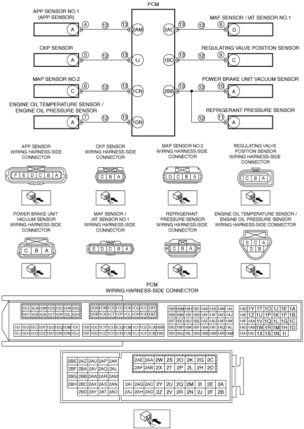
• Verify that the APP sensor and CKP sensor and MAP sensor No.2 and engine oil temperature sensor/engine oil pressure sensor and MAF sensor/IAT sensor No.1 and regulating valve position sensor and power brake unit vacuum sensor and refrigerant pressure sensor connectors are disconnected.
• Inspect for continuity between the following terminals (wiring harness-side) and body ground:
-
― APP sensor terminal A
― CKP sensor terminal A
― MAP sensor No.2 terminal C
― Engine oil temperature sensor/engine oil pressure sensor terminal A
― MAF sensor/IAT sensor No.1 terminal D
― Regulating valve position sensor terminal C
― Power brake unit vacuum sensor terminal A
― Refrigerant pressure sensor terminal A
• Is there continuity?
|
Yes
|
If the short to ground circuit could be detected in the wiring harness:
• Refer to the wiring diagram and verify whether or not there is a common connector between the following terminals:
-
― APP sensor terminal A—PCM terminal 2AM
― CKP sensor terminal A—PCM terminal 1J
― MAP sensor No.2 terminal C—PCM terminal 1CN
― Engine oil temperature sensor/engine oil pressure sensor terminal A—PCM terminal 1DN
― MAF sensor/IAT sensor No.1 terminal D—PCM terminal 2AC
― Regulating valve position sensor terminal C—PCM terminal 1BO
― Power brake unit vacuum sensor terminal A—PCM terminal 2BB
― Refrigerant pressure sensor terminal A—PCM terminal 2BB
If there is a common connector:
-
― Determine the malfunctioning part by inspecting the common connector and the terminal for corrosion, damage, or pin disconnection, and the common wiring harness for a short to ground.
― Repair or replace the malfunctioning part.
If there is no common connector:
-
― Repair or replace the wiring harness which has a short to ground.
If the short to ground circuit could not be detected in the wiring harness:
• Replace the PCM (short to ground in the PCM internal circuit).
Go to Step 14.
|
|
No
|
Go to the next step.
|
|
13
|
INSPECT PCM CONNECTOR CONDITION
• Disconnect the PCM connector.
• Inspect for poor connection (such as damaged/pulled-out pins, corrosion).
• Is there any malfunction?
|
Yes
|
Repair or replace the connector and/or terminals, then go to the next step.
|
|
No
|
Go to the next step.
|
|
14
|
VERIFY DTC TROUBLESHOOTING COMPLETED
• Always reconnect all disconnected connectors.
• Clear the DTC from the PCM memory using the M-MDS.
• Switch the ignition ON (engine off) and wait for 30 s or more.
• Perform the DTC Reading Procedure.
• Is the same DTC present?
|
Yes
|
Repeat the inspection from Step 1.
• If the malfunction recurs, replace the PCM.
Go to the next step.
|
|
No
|
Go to the next step.
|
|
15
|
VERIFY AFTER REPAIR PROCEDURE
• Perform the “AFTER REPAIR PROCEDURE”.
• Are any DTCs present?
|
Yes
|
Go to the applicable DTC inspection.
|
|
No
|
DTC troubleshooting completed.
|