 |
am3zzw00013606
PCM REMOVAL/INSTALLATION [SKYACTIV-D 2.2]
id0140z7802400
PCM Replacement
Replacement procedure determination
|
Step |
Action |
Results |
Action |
|---|---|---|---|
|
1
|
Perform the PCM configuration and verify if the As-Built data input screen is displayed or not.
|
Not displayed
|
Go to “Procedure for PCM replacement (pattern 1)”.
|
|
Displayed
|
Go to “Procedure for PCM replacement (pattern 2)”.
|
Procedure for PCM replacement (pattern 1)
|
Step |
Action |
Page |
|---|---|---|
|
1
|
Continue to perform the configuration.
|
—
|
|
2
|
Clear the DTCs.
|
|
|
3
|
Wait for 20 s or more.
|
—
|
|
4
|
Perform the immobilizer system-related part programming.
|
|
|
5
|
Perform the KOEO self test.
|
|
|
6
|
Perform the KOER self test.
|
|
|
7
|
Perform the Battery Condition Initialization Setting (i-stop setting) Procedure.
|
|
|
8
|
Perform the “FUEL INJECTOR INJECTION AMOUNT CORRECTION” procedure.
|
Procedure for PCM replacement (pattern 2)
|
Step |
Action |
Page |
|---|---|---|
|
1
|
Perform the configuration using the As-Built data.
|
|
|
2
|
Store the identification number of the fuel injector equipped to the vehicle.
|
—
|
|
3
|
Perform the fuel injector code programming.
|
|
|
4
|
Perform the PCM data reset procedure.
|
|
|
5
|
Perform the immobilizer system-related part programming.
|
|
|
6
|
Clear the DTCs.
|
|
|
7
|
Wait for 20 s or more.
|
—
|
|
8
|
Perform the KOEO self test.
|
|
|
9
|
Perform the KOER self test.
|
|
|
10
|
Perform the Battery Condition Initialization Setting (i-stop setting) Procedure.
|
|
|
11
|
Perform the “FUEL INJECTOR INJECTION AMOUNT CORRECTION” procedure.
|
|
|
12
|
Perform compulsory DPF regeneration.
|
|
|
13
|
Perform the following procedure:
1. Warm up the engine until the engine coolant temperature is 70 °C {158 °F} or more.
2. Switch the ignition off.
3. Store “Complete (delete record)” the M-MDS session.
4. Remove the M-MDS.
5. Start the engine.
6. Leave for 3 min while idling.
7. Continuously drive the vehicle for 30 s at a vehicle speed of 50 km/h {31 mph} or more.
8. After stopping the vehicle, leave it idling for 3 min without stopping the engine.
9. Continuously drive the vehicle for 30 s at a vehicle speed of 50 km/h {31 mph} or more again.
|
—
|
|
14
|
Verify that the learning value (O2S11_CAL) for the A/F sensor is other than 0.
― If the learning value (O2S11_CAL) for the A/F sensor is 0, repeat from step 5 of the procedure in Step 13 (start the engine).
|
|
|
15
|
Clear the DTCs.
|
|
|
16
|
Replace the engine oil.
|
Without Set Bolt
am3zzw00013606
|
1. Disconnect the negative battery cable. (See NEGATIVE BATTERY CABLE DISCONNECTION/CONNECTION [SKYACTIV-D 2.2].)
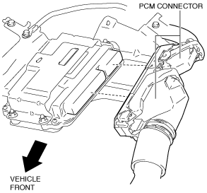
2. Disconnect the PCM connectors. (See PCM Connector Connection Note.)
am3zzw00013607
|
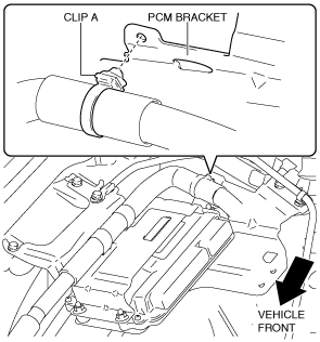
3. Remove the clip A from the PCM bracket.
am3zzw00013608
|
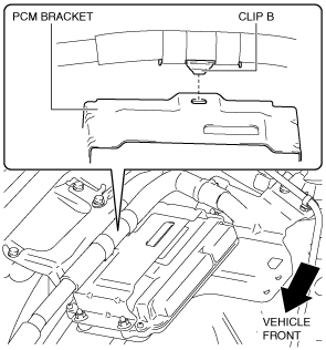
4. Remove the clip B from the PCM bracket.
am3zzw00013609
|
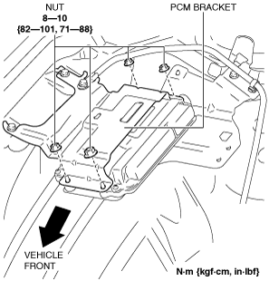
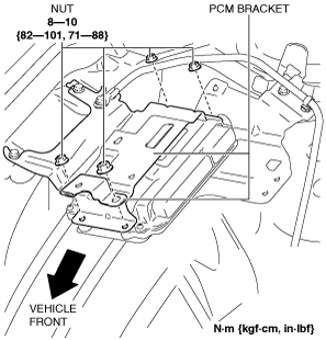
5. Remove the nut from the PCM bracket.
am3zzw00013610
|
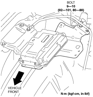
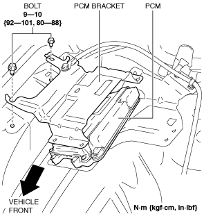
6. Loosen the bolt.
am3zzw00017927
|
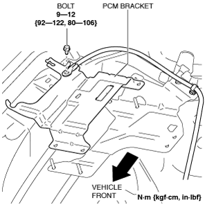
7. Remove the bolts. (See PCM Bracket Installation Note.)
am3zzw00013611
|
8. Set the PCM bracket aside. (See PCM Bracket Installation Note.)
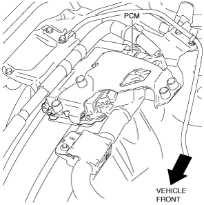
9. Remove the PCM.
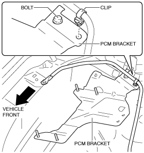
10. Remove the bolt.
am3zzw00017839
|
11. Remove the clip from the PCM bracket.
am3zzw00017840
|
12. Remove the bolt. (See PCM Bracket Installation Note.)
13. Remove the PCM bracket.
14. Install in the reverse order of removal.
15. When replacing the PCM on the vehicles, perform the “PCM Replacement”. (See PCM Replacement.)
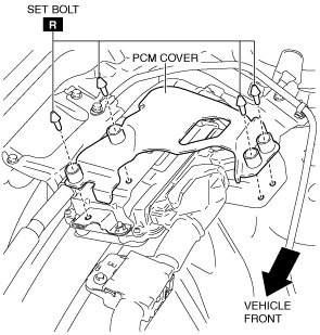
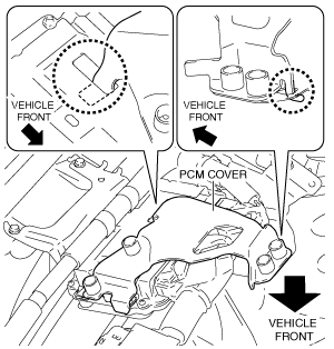
With Set Bolt
am3zzw00013612
|
1. Disconnect the negative battery cable. (See NEGATIVE BATTERY CABLE DISCONNECTION/CONNECTION [SKYACTIV-D 2.2].)
2. Remove the set bolts. (See Set Bolt Removal Note.) (See Set Bolt Installation Note.)
am3zzw00013613
|
3. Remove the PCM cover. (See PCM Cover Installation Note.)
4. Disconnect the PCM connectors. (See PCM Connector Connection Note.)
am3zzw00017928
|
5. Remove the clip A from the PCM bracket.
am3zzw00013614
|
6. Remove the clip B from the PCM bracket.
am3zzw00014279
|
7. Remove the nut from the PCM bracket.
am3zzw00013616
|
8. Loosen the bolt.
am3zzw00017929
|
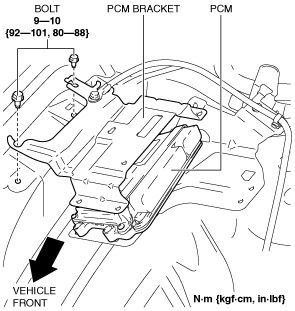
9. Remove the bolts. (See PCM Bracket Installation Note.)
am3zzw00013617
|
10. Set the PCM bracket aside. (See PCM Bracket Installation Note.)
11. Remove the PCM.
12. Remove the bolt.
am3zzw00017839
|
13. Remove the clip from the PCM bracket.
am3zzw00017840
|
14. Remove the bolt. (See PCM Bracket Installation Note.)
15. Remove the PCM bracket.
16. Install in the reverse order of removal.
17. When replacing the PCM on the vehicles, perform the “PCM Replacement”. (See PCM Replacement.)
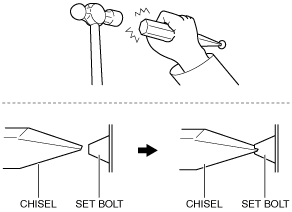
Set Bolt Removal Note
1. Using a chisel and a hammer, cut a groove on the head of the set bolt so that a screwdriver can be inserted.
2. Loose the set bolt using an impact screwdriver or pliers.
am6zzw00010942
|
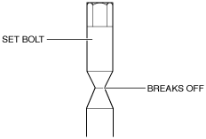
Set Bolt Installation Note
1. Install a new set bolt and tighten it until the neck of the bolt breaks off.
am3zzw00016853
|
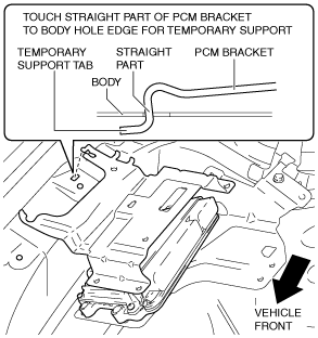
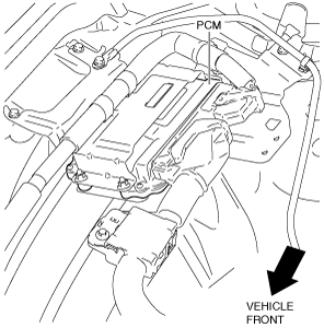
PCM Bracket Installation Note
1. Install the PCM bracket as shown in the figure.
am3zzw00013618
|
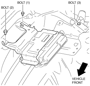
2. Install the bolts using the following procedure:
am3zzw00013619
|
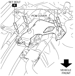
PCM Cover Installation Note
1. Install the PCM cover as shown in the figure.
am3zzw00013620
|
2. Temporarily tighten the four bolts, then completely tighten them.
am3zzw00013621
|
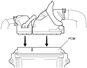
PCM Connector Connection Note
am6zzw00011737
|
1. Set the PCM connector to the position shown in the figure.
am6zzw00011738
|
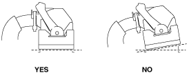
2. Align the PCM connector straight against the connection surface.
am6zzw00011739
|
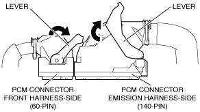
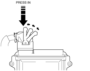
3. Insert the PCM connector straight and press it in until the lever moves up naturally. (Front harness-side connector)
am6zzw00011740
|
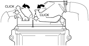
4. Press the PCM connector lever until a click sound is heard.
ac5wzw00004480
|