|
1
|
VERIFY RELATED SERVICE INFORMATION AVAILABILITY
• Verify related Service Information availability.
• Is any related Service Information available?
|
Yes
|
Perform repair or diagnosis according to the available Service Information.
• If the vehicle is not repaired, go to the next step.
|
|
No
|
Go to the next step.
|
|
2
|
VERIFY RELATED PENDING CODE AND/OR DTC
• Switch the ignition off, then ON (engine off).
• Perform the Pending Trouble Code Access Procedure and DTC Reading Procedure.
• Are any other PENDING CODEs and/or DTCs present?
|
Yes
|
Go to the applicable PENDING CODE or DTC inspection.
|
|
No
|
Go to the next step.
|
|
3
|
INSPECT CURRENT SENSOR CONNECTOR CONDITION
-
Note
-
• Always disconnect current sensor connector before disconnecting the negative battery cable.
• Switch the ignition off.
• Disconnect the current sensor connector.
• Inspect for poor connection (such as damaged/pulled-out pins, corrosion).
• Is there any malfunction?
|
Yes
|
Repair or replace the connector and/or terminals, then go to Step 10.
|
|
No
|
Go to the next step.
|
|
4
|
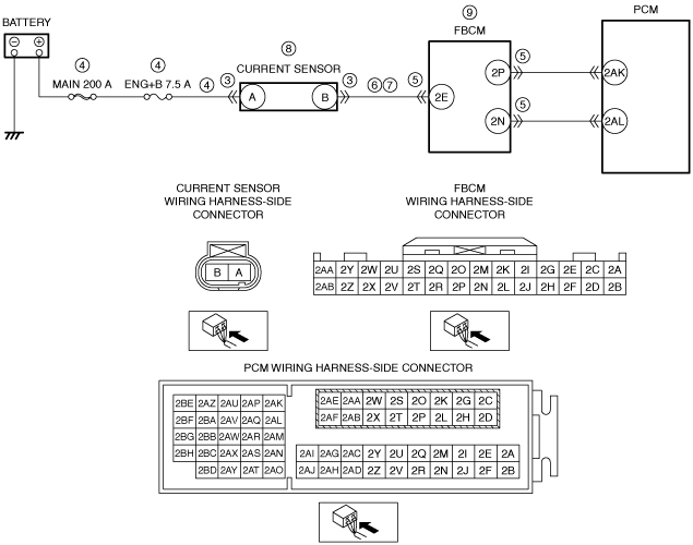
INSPECT CURRENT SENSOR POWER SUPPLY CIRCUIT FOR SHORT TO GROUND OR OPEN CIRCUIT
• Verify that the current sensor connector is disconnected.
• Measure the voltage at the current sensor terminal A (wiring harness-side).
• Is the voltage B+?
|
Yes
|
Go to the next step.
|
|
No
|
Inspect the MAIN 200 A fuse and ENG+B 7.5 A fuse.
• If the fuse is blown:
-
― Refer to the wiring diagram and verify whether or not there is a common connector between MAIN 200 A fuse and current sensor terminal A.
If there is a common connector:
-
• Determine the malfunctioning part by inspecting the common connector and the terminal for corrosion, damage, or pin disconnection, and the common wiring harness for a short to ground.
• Repair or replace the malfunctioning part.
If there is no common connector:
-
• Repair or replace the wiring harness which has a short to ground.
• Replace the fuse.
• If the fuse is damaged:
-
― Replace the fuse.
• If all fuses are normal:
-
― Refer to the wiring diagram and verify whether or not there is a common connector between battery positive terminal and current sensor terminal A.
If there is a common connector:
-
• Determine the malfunctioning part by inspecting the common connector and the terminal for corrosion, damage, or pin disconnection, and the common wiring harness for an open circuit.
• Repair or replace the malfunctioning part.
If there is no common connector:
-
• Repair or replace the wiring harness which has an open circuit.
Go to Step 10.
|
|
5
|
INSPECT FRONT BODY CONTROL MODULE (FBCM) CONNECTOR CONDITION
• Disconnect the front body control module (FBCM) connector.
• Inspect for poor connection (such as damaged/pulled-out pins, corrosion).
• Is there any malfunction?
|
Yes
|
Repair or replace the connector and/or terminals, then go to Step 10.
|
|
No
|
Go to the next step.
|
|
6
|
INSPECT CURRENT SENSOR SIGNAL CIRCUIT FOR SHORT TO GROUND
• Verify that the current sensor and front body control module (FBCM) connectors are disconnected.
• Inspect for continuity between current sensor terminal B (wiring harness-side) and body ground.
• Is there continuity?
|
Yes
|
Refer to the wiring diagram and verify whether or not there is a common connector between current sensor terminal B and front body control module (FBCM) terminal 2E.
If there is a common connector:
• Determine the malfunctioning part by inspecting the common connector and the terminal for corrosion, damage, or pin disconnection, and the common wiring harness for a short to ground.
• Repair or replace the malfunctioning part.
If there is no common connector:
• Repair or replace the wiring harness which has a short to ground.
Go to Step 10.
|
|
No
|
Go to the next step.
|
|
7
|
INSPECT CURRENT SENSOR SIGNAL CIRCUIT FOR OPEN CIRCUIT
• Verify that the current sensor and front body control module (FBCM) connectors are disconnected.
• Inspect for continuity between current sensor terminal B (wiring harness-side) and front body control module (FBCM) terminal 2E (wiring harness-side).
• Is there continuity?
|
Yes
|
Go to the next step.
|
|
No
|
Refer to the wiring diagram and verify whether or not there is a common connector between current sensor terminal B and front body control module (FBCM) terminal 2E.
If there is a common connector:
• Determine the malfunctioning part by inspecting the common connector and the terminal for corrosion, damage, or pin disconnection, and the common wiring harness for an open circuit.
• Repair or replace the malfunctioning part.
If there is no common connector:
• Repair or replace the wiring harness which has an open circuit.
Go to Step 10.
|
|
8
|
INSPECT CURRENT SENSOR
• Inspect the current sensor.
• Is there any malfunction?
|
Yes
|
Replace the current sensor, then go to Step 10.
|
|
No
|
Go to the next step.
|
|
9
|
INSPECT FRONT BODY CONTROL MODULE (FBCM)
• Inspect the front body control module (FBCM).
• Is there any malfunction?
|
Yes
|
Replace the front body control module (FBCM), then go to the next step.
|
|
No
|
Go to the next step.
|
|
10
|
VERIFY DTC TROUBLESHOOTING COMPLETED
• Always reconnect all disconnected connectors.
• Clear the DTC from the PCM memory using the M-MDS.
• Implement the repeatability verification procedure.
• Perform the DTC Reading Procedure.
• Is the same DTC present?
|
Yes
|
Repeat the inspection from Step 1.
|
|
No
|
Go to the next step.
|
|
11
|
VERIFY AFTER REPAIR PROCEDURE
• Perform the “AFTER REPAIR PROCEDURE”.
• Are any DTCs present?
|
Yes
|
Go to the applicable DTC inspection.
|
|
No
|
DTC troubleshooting completed.
|