OIL PUMP REMOVAL/INSTALLATION [SKYACTIV-D 2.2]
id0111s6800600
-
Warning
-
• Hot engines and engine oil can cause severe burns. Turn off the engine and wait until it and the engine oil have cooled.
• A vehicle that is lifted but not securely supported on safety stands is dangerous. It can slip or fall, causing death or serious injury. Never work around or under a lifted vehicle if it is not securely supported on safety stands.
• Continuous exposure to USED engine oil has caused skin cancer in laboratory mice. Protect your skin by washing with soap and water immediately after working with engine oil.
1. Turn the steering wheel completely to the right.
2. Remove the front under cover No.2. (See FRONT UNDER COVER No.2 REMOVAL/INSTALLATION.)
3. Remove the splash shield No.1 (RH). (See SPLASH SHIELD REMOVAL/INSTALLATION.)
4. Drain the engine oil. (See ENGINE OIL REPLACEMENT [SKYACTIV-D 2.2].)
5. Remove the oil pan. (See OIL PAN REMOVAL/INSTALLATION [SKYACTIV-D 2.2].)
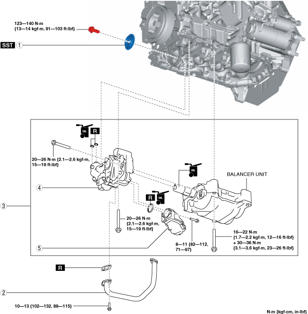
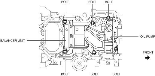
6. Remove in the order indicated in the table.
7. Install in the reverse order of removal.
8. Refill with the specified type and amount of the engine oil. (See ENGINE OIL REPLACEMENT [SKYACTIV-D 2.2].)
9. Start the engine and confirm that there is no oil leakage.
-
• If there is oil leakage, repair or replace the applicable part.
10. Inspect the oil level. (See ENGINE OIL LEVEL INSPECTION [SKYACTIV-D 2.2].)
11. Inspect the oil pressure. (See OIL PRESSURE INSPECTION [SKYACTIV-D 2.2].)
|
1
|
Oil pump driven sprocket
|
|
2
|
Oil pipe
|
|
3
|
Balancer component
|
|
4
|
Oil pump
|
|
5
|
Oil strainer
|
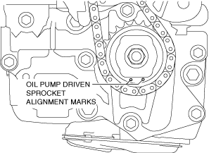
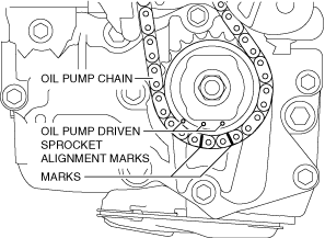
Oil pump driven sprocket removal note
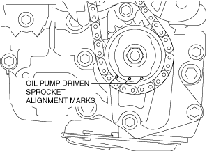
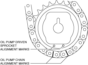
1. Rotate the crankshaft and align the oil pump driven sprocket alignment marks to the positions shown in the figure.
Tyep A
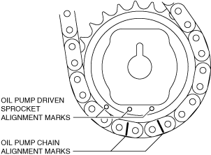
Type B
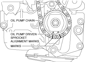
2. Place marks on the oil pump chain next to the oil pump driven sprocket alignment marks.
Type A
Type B
-
Note
-
• The marks will be used as alignment marks when installing the oil pump driven sprocket.
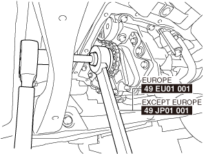
3. While locking the oil pump driven sprocket against rotation using the SST, remove the oil pump driven sprocket installation bolt.
4. Remove the oil pump driven sprocket.
Oil pump, balancer unit installation note
-
Caution
-
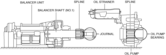
• If the balancer shaft (No.1) spline is scratched or damaged, the engagement with the oil pump spline could worsen and it may not be possible to assemble the oil pump. Therefore, be careful not to scratch or damage the spline.
• Because the balancer shaft (No.1) journal slides with oil pump bearing, if the journal is scratched or damaged, the bearing could become damaged. Therefore, be careful not to scratch or damage the journal.
1. Install the oil pump and balancer component using the following procedure:
- (1) Apply clean engine oil to a new oil strainer O-ring.
-
- (2) Assemble the oil strainer to the oil pump.
-
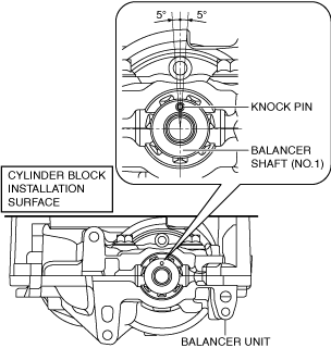
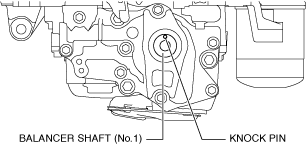
- (3) Verify that the balancer shaft (No.1) knock pin position is perpendicular to the cylinder block installation surface.
-
-
• If the knock pin position has deviated, rotate the balancer shaft (No.1) and correct.
- (4) Apply engine oil to the balancer shaft (No.1) journal area.
-
- (5) Align the heights of the balancer shaft (No.1) spline and oil pump spline and install the oil pump to the balancer unit.
-
-
Note
-
• The balancer shaft (No.1) spline and oil pump spline timing does not need to be matched.
- (6) Temporarily tighten the bolts until the seating surfaces of the oil pump installation bolts are completely seated.
-
- (7) Install the oil pump and balancer unit to the cylinder block and temporarily tighten the seating face of the bolts shown in the figure until they are completely seated.
-
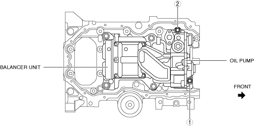
- (8) Tighten oil pump installation bolts in the order shown in the figure to the specified torque.
-
-
Tightening torque
-
20—26 N·m {2.1—2.6 kgf·m, 15—19 ft·lbf}
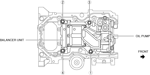
- (9) Tighten the balancer unit installation bolts in two steps in the order shown in the figure to the specified torque.
-
-
Tightening torque
-
First step: 16—22 N·m {1.7—2.2 kgf·m, 12—16 ft·lbf}
Second step: 30—36 N·m {3.1—3.6 kgf·m, 23—26 ft·lbf}
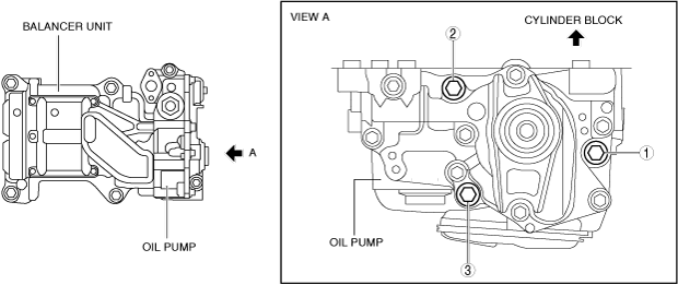
- (10) Tighten the oil pump installation bolts in the order shown in the figure.
-
-
Tightening torque
-
20—26 N·m {2.1—2.6 kgf·m, 15—19 ft·lbf}
Oil pump driven sprocket installation note
1. Verify that the knock pin is aligned to the position shown in the figure.
-
• If it is not in the position shown in the figure, rotate the balancer shaft (No.1) and adjust the knock pin position.
-
Note
-
• When rotating the balancer shaft (No.1), temporarily assemble the oil pump driven sprocket and rotate while holding the sprocket with a hand.
2. Align the oil pump chain alignment marks with the oil pump driven sprocket alignment marks.
Type A
Type B
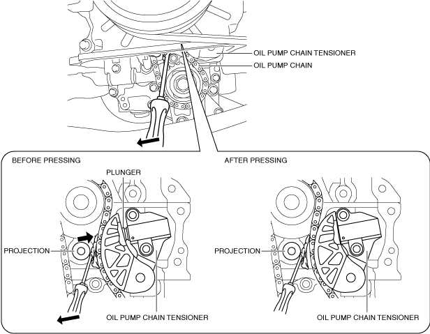
3. Install the oil pump chain and oil pump driven sprocket as a single unit using the following procedure.
- (1) Press in the plunger of the oil pump chain tensioner as shown in the figure using a screwdriver wrapped in a cloth.
-
- (2) While pressing in the plunger of the oil pump chain tensioner, install the oil pump driven sprocket.
-
- (3) While locking the oil pump driven sprocket against rotation using the SST, tighten the oil pump driven sprocket installation bolt.
-
-
Tightening torque
-
123—140 N·m {13—14 kgf·m, 91—103 ft·lbf}