 |
TURBOCHARGER SOLENOID VALVE INSPECTION [SKYACTIV-D 1.5]
id0113q2991900
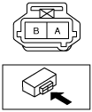
Resistance inspection
1. Disconnect the negative battery cable. (See NEGATIVE BATTERY CABLE DISCONNECTION/CONNECTION [SKYACTIV-D 1.5].)
2. Remove the turbocharger solenoid valve. (See TURBOCHARGER SOLENOID VALVE REMOVAL/INSTALLATION [SKYACTIV-D 1.5].)
3. Measure resistance between turbocharger solenoid valve terminals A and B.
ac5jjw00003488
|
Airflow Inspection
1. Disconnect the negative battery cable. (See NEGATIVE BATTERY CABLE DISCONNECTION/CONNECTION [SKYACTIV-D 1.5].)
2. Remove the turbocharger solenoid valve. (See TURBOCHARGER SOLENOID VALVE REMOVAL/INSTALLATION [SKYACTIV-D 1.5].)
3. Inspect airflow between the ports under the following conditions.
am3zzw00017990
|
|
Measured condition*1 |
Continuity between ports |
|---|---|
|
While covering port A, apply pressure to port B
|
No airflow between ports B and C*2
|
PID/DATA Monitor Inspection
1. Connect the M-MDS to the DLC-2.
2. Start the engine.
3. Access the PID/DATA monitor item VGTURB_ACT and simulation item VGTURB_DSD using the M-MDS. (See ON-BOARD DIAGNOSTIC TEST [SKYACTIV-D 1.5].)
4. Verify that the value of the conforming PID VGTURB_ACT increases when the simulation item VGTURB_DSD value is increased.