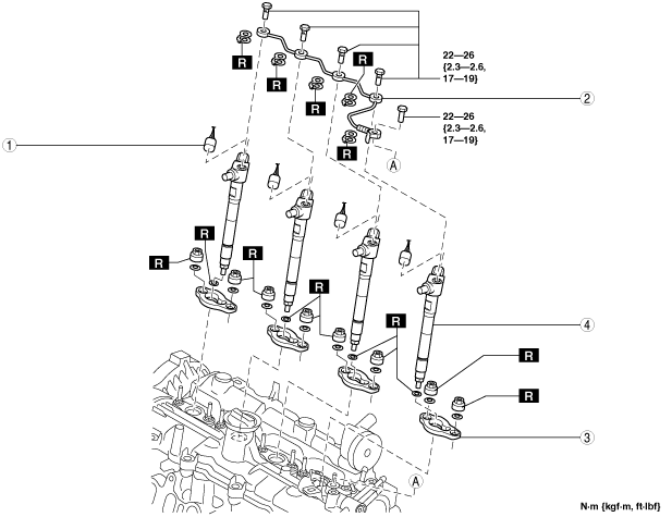
FUEL INJECTOR REMOVAL/INSTALLATION [SKYACTIV-D 2.2]


id0114z7800600

Warning
•  Highly pressurized fuel may spray out if the fuel line is cut. Due to the following dangers occurring with a fuel spray, always complete the “Fuel Line Safety Procedure” to prevent the fuel from spraying.
―  Fuel may cause irritation if it comes in contact with skin and eyes.
―  If fuel ignites and causes a fire, it may lead to serious injury or death, and damage to property and facilities.
•  A person charged with static electricity could cause a fire or explosion, resulting in death or serious injury. Before servicing the fuel system, make sure to discharge static electricity by touching a vehicle.
Caution
•  If parts are exposed to the fuel, their function may be decreased or a fire may occur. Spread a rag to absorb any leaked fuel.
•  Do not let foreign matter get into the injection pipe to prevent clogging. In addition, always install the injection pipe to the specified tightening torque.
Note
•  If the fuel injector is replaced, perform the “Operation After Replacing Fuel Injector”.

Operation After Replacing Fuel Injector

1.  If the fuel injector is replaced, perform the following procedure.

STEP

ACTION

PAGE/CONDITION

1
Perform fuel injector code programming.
2
Perform fuel injector data reset procedure.
3
Clear the DTCs.
4
Wait for 20 s.
5
Perform KOEO self-test procedure.
6
Perform KOER self-test procedure.
7
Perform fuel injector injection amount correction.
8
Clear the DTCs.


Fuel injector Removal/Installation

1.  Disconnect the negative battery cable. (See NEGATIVE BATTERY CABLE DISCONNECTION/CONNECTION [SKYACTIV-D 2.2].)

2.  Perform the “Fuel Line Safety Procedure” referring to the “BEFORE SERVICE PRECAUTION”. (See BEFORE SERVICE PRECAUTION [SKYACTIV-D 2.2].)

3.  Remove the engine cover. (See ENGINE COVER REMOVAL/INSTALLATION [SKYACTIV-D 2.2].)

4.  Disconnect the CMP sensor connector.

5.  Remove the injection pipe (fuel injector side). (See INJECTION PIPE REMOVAL/INSTALLATION [SKYACTIV-D 2.2].)

6.  Remove in the order shown in the figure.

7.  Install in the reverse order of removal.

8.  Refer to the “AFTER SERVICE PRECAUTION” and perform the fuel hose installation procedure and fuel line air bleeding. (See AFTER SERVICE PRECAUTION [SKYACTIV-D 2.2].)

am3zzw00016416

1
Fuel injector connector
2
Fuel return pipe (fuel injector side)
3
Fuel injector bracket
4
Fuel injector


Fuel injector removal note

Caution
•  Do not apply excessive force to the bar to prevent damaging the cylinder head cover which the socket is set to.

1.  If it is difficult to remove the fuel injector, use a bar and socket set up as shown in the figure as leverage to lift the fuel injector bracket and then remove the fuel injector.

ac5wzw00008450

Note
•  Set the bar on the socket with the socket as the fulcrum point.


Fuel injector installation note

Note
•  Clean the injector hole and the bore using the following procedure and the SSTs (49 0000 203) shown in the figure.
am6xuw00012307

1
Round wire brush
2
Fleece brush
3
Wire brush
4
Blanking plug
5
Extension bar
6
Flexible shaft
7
Holder

1.  Install the blanking plug to the end of the extension bar.

2.  Insert the blanking plug into the injector hole, rotate the extension bar counterclockwise, and then block the injector hole using the blanking plug.

am6xuw00012308

3.  Install the round wire brush to the end of the flexible shaft.

am6xuw00012309

Caution
•  Install the holder and clean the bore to prevent damage to the bore.
am6xuw00012310

4.  Connect the flexible shaft installed to the round wire brush to the drill, and clean the bore.

5.  Clean the carbon that was cut off using an air gun.

6.  Cut (reference: diameter approx. 23 mm) the fleece brush so that it reaches the bottom surface, and install it to the flexible shaft.

Caution
•  Clean the bottom surface while verifying the cleaning surface condition. If the bottom surface is cleaned excessively, it could be damaged.

7.  Connect the flexible shaft installed to the fleece brush to the drill, and clean the bottom surface.

am6xuw00012311

8.  Clean the carbon that was cut off using an air gun.

9.  Insert the extension bar and remove the blanking plug.

10.  Clean the injector hole using a wire brush.

am6xuw00012312

11.  Temporarily install the fuel injector and the fuel injector bracket.

ac5wzw00005294

12.  Loosen the common rail.

13.  Temporarily tighten the new injection pipe (fuel injector side).

14.  Tighten the new fuel injector bracket installation nuts using the following procedure.

Caution
•  If the fuel injector bracket installation nuts are tightened incorrectly, it could damage the fuel injector bracket and cause gas leakage due to incorrect installation. To prevent this, tighten the fuel injector bracket installation nuts using the following procedure.
Note
Fuel injector bracket installation nut type A
•  A paint mark for tightening to the specified angle is indicated on the fuel injector bracket installation nuts (angle between same colored paint marks is 230° as shown in figure).
am3zzw00016417
Fuel injector bracket installation nut type B
•  There is a scribe line engraved on the fuel injector bracket installation nut for tightening it to the specified angle. (The angles between the white paint mark and scribe line A, and between the yellow paint mark and scribe line B are both 230 degrees as shown in the figure)
ac5wzw00011711
•  Tighten only the fuel injector bracket installation nuts on the engine rear side to the specified angle.
(1)  Temporarily tighten the nut on the engine front side (until nut is seated).
am3zzw00016418
(2)  Completely tighten the nut on the engine front side.
Tightening torque
2.0 N·m {20 kgf·cm, 18 in·lbf}
(3)  Loosen the nut on the engine front side 90°.
(4)  Temporarily tighten the nut on the engine rear side (until nut is seated).
(5)  Completely tighten the nut on the engine rear side.
Tightening torque
2.0 N·m {20 kgf·cm, 18 in·lbf}
(6)  Draw a line on the fuel injector bracket at a right angle to the paint mark (either yellow or white) on the nut surface on the engine rear side. (fuel injector bracket installation nut type A)
am3zzw00016419
Note
•  The drawn line on the fuel injector bracket is the standard angle to which the nut is tightened.
am3zzw00016420
(7)  Draw a line on the fuel injector bracket at a right angle to the center of the scribe line (either A or B) on the surface of the nut on the rear side of the engine. (fuel injector bracket installation nut type B)
am3zzw00020783
Note
•  The drawn line on the fuel injector bracket is the standard angle to which the nut is tightened.
am3zzw00016420
(8)  Tighten the nut until the paint mark (same color step (6) or (7)) on the nut upper surface on the engine rear side comes to the position of the drawn line on the fuel injector bracket.
am3zzw00016421

Note
•  After tightening the nut following the procedure, the bolt projections differ as shown in the figure because the fuel injector bracket leans a little. This is the correct condition and retightening is not required.
aaxjjw00018823

15.  Tighten the injection pipes (fuel injector side) on the common rail side.

Tightening torque for injection pipe (fuel injector side)
32—42 N·m {3.3—4.2 kgf·m, 24—30 ft·lbf}

16.  Tighten the injection pipes (fuel injector side) on the fuel injector side.

Tightening torque for injection pipe (fuel injector side)
32—42 N·m {3.3—4.2 kgf·m, 24—30 ft·lbf}

17.  Tighten the common rail.

Common rail tightening torque
20—26 N·m {2.1—2.6 kgf·m, 15—19 ft·lbf}

18.  Tighten the fuel return pipe (fuel injector side) in the order shown in the figure.

am3zzw00016393

Fuel return pipe (fuel injector side) tightening torque
22—26 N·m {2.3—2.6 kgf·m, 17—19 ft·lbf}