GENERATOR INSPECTION [SKYACTIV-D 2.2 (WITHOUT i-ELOOP)]
id0117h68003i4
-
Caution
-
• Do not apply direct battery positive voltage to generator terminal 2B, otherwise it could cause damage to the internal parts (power transistor) of the generator.
-
Note
-
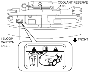
• The i-ELOOP caution label is adhered to the position shown in the figure below on vehicles with i-ELOOP. When determining if a vehicle in for servicing is equipped with i-ELOOP, refer to the i-ELOOP section. (See
GENERATOR INSPECTION [SKYACTIV-D 2.2 (WITH i-ELOOP)])
Charging System Warning Light
1. Verify that the battery is fully charged. (See BATTERY INSPECTION [SKYACTIV-D 2.2].)
2. Verify that the assembly condition of the drive belt is normal. (See DRIVE BELT INSPECTION [SKYACTIV-D 2.2].)
3. Switch the ignition ON (engine off), verify that the charging system warning light illuminates.
-
• If it does not illuminate, inspect the charging system warning light and the wiring harness.
-
― If the charging system warning light and the wiring harness are normal, inspect the PCM.
4. Verify that the charging system warning light turns off after the engine is started.
-
Generator
Generator voltage inspection
1. Verify that the battery is fully charged. (See BATTERY INSPECTION [SKYACTIV-D 2.2].)
2. Verify that the assembly condition of the drive belt is normal. (See DRIVE BELT INSPECTION [SKYACTIV-D 2.2].)
3. Turn off all electrical loads.
4. Start the engine.
5. Verify that the generator rotates smoothly without any noise while the engine is running.
-
• If there is any noise, find the cause and repair or replace the generator.
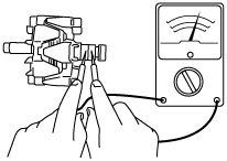
6. Measure the voltage at each terminal using a tester.
-
• If not as specified, find the cause and repair or replace the applicable part.
-
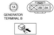
Generator standard voltage [IG-ON]
-
Terminal 1A: B+
Terminal 2A: Approx. 1 V or less
Terminal 2B: Approx. 0 V
-
Generator standard voltage [Idle, 20 °C {68 °F}]
-
Terminal 1A: 13—15 V
Terminal 2A: Approx. 3—8 V
Terminal 2B: Turn the electrical loads (such as headlights, blower motor, rear window defroster, brake lights) on and verify that the voltage reading increases.
Generator current inspection
-
Note
-
• Since the charging current decreases rapidly after starting the engine, carry out the following procedure quickly, and read the maximum current value.
1. Verify that the battery is fully charged. (See BATTERY INSPECTION [SKYACTIV-D 2.2].)
2. Verify that the assembly condition of the drive belt is normal. (See DRIVE BELT INSPECTION [SKYACTIV-D 2.2].)
3. Disconnect the negative battery cable.
4. Connect a tester, which can read 120 A or more, between generator terminal B and generator terminal B cable.
5. Connect the negative battery cable. (See NEGATIVE BATTERY CABLE DISCONNECTION/CONNECTION [SKYACTIV-D 2.2].)
6. Turn off all electrical loads.
7. Start the engine.
-
Note
-
• When the electrical load on the vehicle is low, the specified current cannot be verified although the generator is normal. In this case, increase the electrical load (Leave the headlights turned on for a while, then discharge the battery, or use a similar method.) and recheck.
• If the generator itself or the ambient temperature are too high, the specified current also cannot be verified. In this case, cool down the generator and recheck.
8. Turn the electrical loads (such as headlights, blower motor, rear window defroster, brake lights) on and verify that the current reading increases more than the minimum value indicated below.
-
Generator generated current (reference value) [Ambient temperature: 20 °C {68 °F}, Engine hot]
|
Engine speed (rpm)
|
Terminal 1A voltage (V)
|
Generator output current (A)
|
|
1,000
|
13
|
125
|
|
1,000
|
15
|
128
|
|
2,000
|
13
|
148
|
|
2,000
|
15
|
163
|
* Field coil current control signal 100%
Generator Internal Parts
Rotor
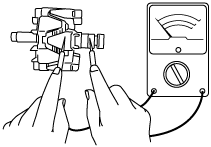
1. Measure the resistance between the slip rings using a ohmmeter.
-
• If not within specification, replace the rotor.
-
Generator rotor resistance (between slip rings) [20 °C {68 °F}]
-
1.8—2.1 ohms
2. Verify that there is no continuity between the slip ring and core using a ohmmeter.
-
• If there is continuity, replace the rotor.
3. Inspect the slip ring surface condition.
-
• If the slip ring surface is rough, use a lathe or fine sandpaper to make it smooth.
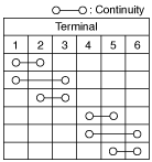
Stator coil
1. Verify that the continuity is as indicated in the table.
-
• If there is any malfunction, replace the stator.
2. Verify that there is no continuity between the stator coil leads and core using a ohmmeter.
-
• If there is continuity, replace the stator coil.
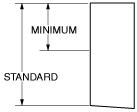
Brush
1. Inspect brushes for wear.
-
• If any brush is worn almost to or beyond the limit, replace all of the brushes.
-
Generator brush length
-
Standard: 22.5 mm {0.886 in}
Minimum: 5.0 mm {0.20 in}
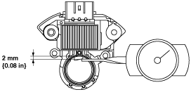
Brush spring
1. Measure the force of the brush spring using a spring pressure gauge.
2. Read the spring pressure gauge at the brush tip projection of 2 mm {0.08 in}.
-
• If not within specification, replace the brush spring.
-
Generator brush spring force
-
Standard: 4.1—5.3 N {0.42—0.54 kgf, 1.0—1.1 lbf}
Minimum: 1.7 N {0.17 kgf, 0.38 lbf}
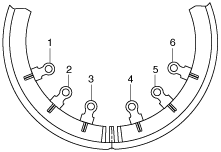
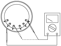
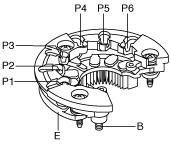
Rectifier (Using an analog circuit tester)
1. Inspect for continuity of the diodes using an analog circuit tester.
-
• If not as specified, replace the rectifier.
Specification
|
Negative
|
Positive
|
Continuity
|
|
E
|
P1, P2, P3, P4, P5, P6
|
Yes
|
|
B
|
No
|
|
P1, P2, P3, P4, P5, P6
|
E
|
No
|
|
B
|
Yes
|
Rectifier (Using a digital circuit tester)
1. Inspect for continuity of the diodes using a digital circuit tester.
-
• If not as specified, replace the rectifier.
Specification
|
Negative
|
Positive
|
Continuity
|
|
E
|
P1, P2, P3, P4, P5, P6
|
No
|
|
B
|
Yes
|
|
P1, P2, P3, P4, P5, P6
|
E
|
Yes
|
|
B
|
No
|
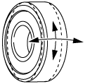
Bearing
1. Inspect for abnormal noise, looseness, and sticking.
-
• Replace the bearing if necessary.