 |
am6zzw00010907
GENERATOR INSPECTION [SKYACTIV-D 2.2 (WITH i-ELOOP)]
id131704004003
Charging System Warning Light
1. Verify that the battery is fully charged.
2. Verify that the assembly condition of the drive belt is normal. (See DRIVE BELT INSPECTION [SKYACTIV-D 2.2].)
3. Switch the ignition to ON (engine off), verify that the charging system warning light illuminates.
4. Verify that the charging system warning light goes out after the engine is started.
Generator
Voltage
1. Verify that the battery is fully charged.
2. Verify that the assembly condition of the drive belt is normal. (See DRIVE BELT INSPECTION [SKYACTIV-D 2.2].)
3. Turn off all electrical loads.
4. Start the engine.
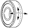
5. Verify that the generator rotates smoothly without any noise while the engine is running.
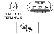
6. Measure the voltage at each terminal using a tester.
am6zzw00010907
|
Current
1. Verify that the battery is fully charged.
2. Verify that the assembly condition of the drive belt is normal. (See DRIVE BELT INSPECTION [SKYACTIV-D 2.2].)
3. Disconnect the negative battery cable.
4. Connect a tester, which can read 120 A or more, between generator terminal B and generator terminal B cable.
5. Connect the negative battery cable. (See NEGATIVE BATTERY CABLE DISCONNECTION/CONNECTION [SKYACTIV-D 2.2].)
6. Turn off all electrical loads.
7. Start the engine.
8. With the electric loads such as headlights, blower motor, rear window defroster, brake lights turned on, verify that the current increases.
Generator generated current maximum value (reference value) [Ambient temperature: 20 °C {68 °F}, Engine hot]
(Vehicle with i-ELOOP)
|
Engine speed (rpm) |
Terminal 1A voltage (V) |
Generator output current (A) |
|---|---|---|
|
1,000
|
15
|
130
|
|
2,000
|
15
|
150
|
Generator Inner Parts
Rotor
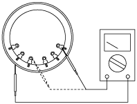
1. Measure the resistance between the slip rings using a tester.
am6zzw00002350
|
2. Verify that there is no continuity between the slip ring and core using a tester.
am6zzw00002351
|
3. Inspect the slip ring surface condition.
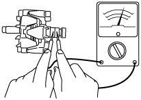
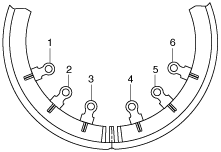
Stator coil
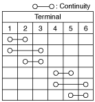
1. Verify that the continuity is as indicated in the table.
am6zzw00002352
|
am6zzw00002353
|
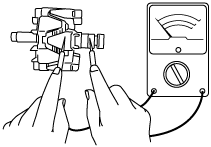
2. Verify that there is no continuity between the stator coil leads and core using a tester.
am3uuw00003268
|
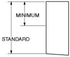
Brush
1. Inspect brushes for wear.
am6zzw00002355
|
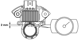
Brush spring
1. Measure the force of the brush spring using a spring pressure gauge.
2. Read the spring pressure gauge at the brush tip projection of 2 mm {0.08 in}.
adejjw00007494
|
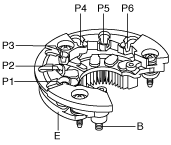
Rectifier (Using an analog circuit tester)
1. Inspect for continuity of the diodes using an analog circuit tester.
adejjw00007495
|
Specification
|
Negative |
Positive |
Continuity |
|---|---|---|
|
E
|
P1, P2, P3, P4, P5, P6
|
Yes
|
|
B
|
No
|
|
|
P1, P2, P3, P4, P5, P6
|
E
|
No
|
|
B
|
Yes
|
Rectifier (Using a digital circuit tester)
1. Inspect for continuity of the diodes using a digital circuit tester.
Specification
|
Negative |
Positive |
Continuity |
|---|---|---|
|
E
|
P1, P2, P3, P4, P5, P6
|
No
|
|
B
|
Yes
|
|
|
P1, P2, P3, P4, P5, P6
|
E
|
Yes
|
|
B
|
No
|
Bearing
1. Inspect for abnormal noise, looseness, and sticking.
am6zzw00002358
|