DTC C0020:11/C0020:12/C0020:13/C0020:71 [ANTILOCK BRAKE SYSTEM (ABS)]


id0402b0906000

DTC
C0020:11, C0020:12, C0020:13, C0020:71
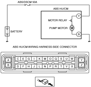
Pump motor, motor relay
DETECTION CONDITION
•  C0020:11
―  Motor relay signal does not correspond to ABS HU/CM OFF signal.
•  C0020:12
―  ABS motor monitor signal does not correspond to ABS HU/CM OFF signal.
―  ABS motor monitor signal does not correspond to ABS HU/CM ON signal.
•  C0020:13
―  Motor relay signal does not correspond to ABS HU/CM ON signal.
•  C0020:71
―  ABS HU/CM motor monitor ON signal is not input within specified time limit or more when motor signal is switched from ON to OFF by ABS HU/CM.
FAIL-SAFE FUNCTION
•  Illuminates the ABS warning light.
•  Inhibits the ABS control.
POSSIBLE CAUSE
•  Fuse (ABS/DSCM 50A) malfunction
•  Open or short circuit in ABS HU/CM internal motor relay, or stuck motor relay
•  Open or short circuit in ABS HU/CM internal pump motor, or frozen pump motor
•  Open circuit or short to ground in the wiring harness between the battery and ABS HU/CM terminal Y
•  Open circuit in the wiring harness between ABS HU/CM terminal B and body ground
•  Poor connection at connectors (female terminal)

Diagnostic procedure

STEP

INSPECTION

ACTION

1
INSPECT FUSE CONDITION
•  Is the fuse (ABS/DSCM 50A) normal?
Yes
Go to the next step.
No
Replace the fuse, then go to Step 6.
2
VERIFY PUMP MOTOR OPERATION
•  Switch the ignition to off.
•  Connect the M-MDS to the DLC-2.
•  Switch the ignition ON (engine off).
•  Access PMP_MT_SP active command modes using the M-MDS.
•  Does the pump motor operate?
Yes
Go to Step 6.
No
Go to the next step.
3
INSPECT MOTOR RELAY POWER SUPPLY FOR OPEN CIRCUIT
•  Switch the ignition to off.
•  Disconnect the ABS HU/CM connector.
•  Inspect for continuity between ABS HU/CM terminal Y (vehicle harness-side) and the positive battery terminal.
•  Is there continuity?
Yes
Go to the next step.
No
Refer to the wiring diagram and verify whether or not there is a common connector between ABS HU/CM terminal Y and the positive battery terminal.
If there is a common connector:
•  Determine the malfunctioning part by inspecting the common connector and the terminal for corrosion, damage, or pin disconnection, and the common wiring harness for an open circuit.
•  Repair or replace the malfunctioning part.
If there is no common connector:
•  Repair or replace the wiring harness which has an open circuit.
Go to Step 6.
4
INSPECT MOTOR RELAY POWER SUPPLY FOR SHORT CIRCUIT
•  Inspect for continuity between ABS HU/CM terminal Y (vehicle harness-side) and body ground.
•  Is there continuity?
Yes
Repair or replace the wiring harness, then go to Step 6.
No
Go to the next step.
5
INSPECT PUMP MOTOR GROUND FOR OPEN CIRCUIT
•  Inspect for continuity between ABS HU/CM terminal B (vehicle harness-side) and body ground.
•  Is there continuity?
Yes
Go to the next step.
No
Repair or replace the wiring harness, then go to the next step.
6
VERIFY THAT THE SAME DTC IS NOT PRESENT
•  Reconnect all disconnected connectors.
•  Clear the DTCs from the memory.
•  Start the engine and drive the vehicle at 10 km/h {6.2 mph} or more.
•  Are the same DTCs present?
Yes
Repeat the inspection from Step 1.
If the malfunction recurs, replace the ABS HU/CM, then go to the next step.
No
Go to the next step.
7
VERIFY THAT NO OTHER DTCS ARE PRESENT
•  Are any other DTCs output?
Yes
Go to the applicable DTC inspection.
No
DTC troubleshooting completed.