 |
am3uuw00010903
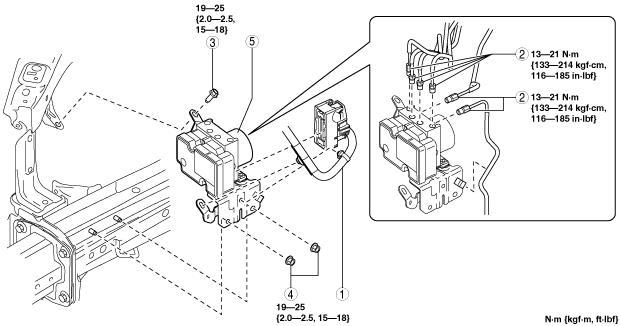
ABS HU/CM REMOVAL/INSTALLATION
id041300801400
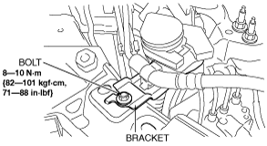
1. Remove the bracket.
am3uuw00010903
|
2. Remove in the order indicated in the table.
3. Install in the reverse order of removal.
4. After installation, add brake fluid, bleed the air, and inspect for fluid leakage. (See BRAKE FLUID AIR BLEEDING.)
5. Perform the ABS related parts sensor initialization procedure (only when replacing it with a new one). (See ABS RELATED PARTS SENSOR INITIALIZATION PROCEDURE.)
6. Clear the DTCs from the memory. (See ON-BOARD DIAGNOSIS [ANTILOCK BRAKE SYSTEM (ABS)].)
am3zzw00015888
|
|
1
|
Connector
(See Connector Removal Note.)
(See Connector Installation Note.)
|
|
2
|
Brake pipe
(See Brake Pipe Removal Note.)
(See Brake Pipe Installation Note.)
|
|
3
|
Bolt
|
|
4
|
Nut
|
|
5
|
ABS HU/CM component
|
am3zzw00015889
|
|
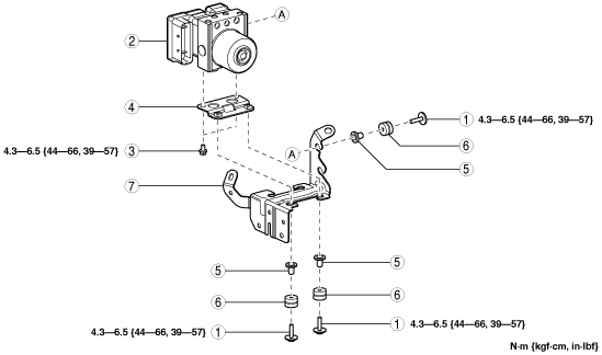
1
|
Bolt
|
|
2
|
ABS HU/CM
|
|
3
|
Bolt
|
|
4
|
Bracket
|
|
5
|
Mount bolt
|
|
6
|
Mount rubber
|
|
7
|
Bracket
|
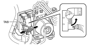
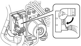
Connector Removal Note
1. Pull the connector cover up in the direction of the arrow while pressing the tabs of the connector cover.
am3zzw00015890
|
2. Pull the connector toward the vehicle rear and remove it.
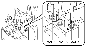
Brake Pipe Removal Note
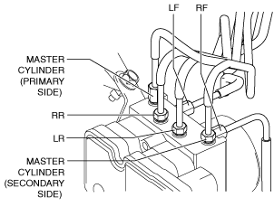
1. Place an alignment marks on the brake pipe and ABS HU/CM.
am3zzw00015891
|
2. Apply protective tape to the connector to prevent brake fluid from entering.
3. Disconnect the brake pipes.
Brake Pipe Installation Note
1. Align the marks made before removal and install the brake pipe to the ABS HU/CM and brake pipe joint referring to the figure.
am3zzw00015892
|
2. Tighten the brake pipe to the specified torque using the commercially available flare nut wrench.
Connector Installation Note
1. Connect the connector and pull the lock lever down in the direction of the arrow.
am3zzw00015893
|
2. After connecting the connector, verify that the connector cover is completely pushed in.