DTC C1109:64 [DYNAMIC STABILITY CONTROL (DSC)]


id0402b2878700

DTC
C1109:64
DSC OFF switch
DETECTION CONDITION
•  Continuous ON signal from the DSC OFF switch for 10 s or more is detected.
FAIL-SAFE FUNCTION
•  Permits the control and does not illuminate each warning/indicator light.
POSSIBLE CAUSE
•  The driver pressed and held the DSC OFF switch for 10 s or more.
•  Short to ground in the wiring harness between the instrument cluster terminal V and DSC OFF switch terminal B
•  Open circuit in wiring harness between instrument cluster terminal T and DSC OFF switch terminal C
•  DSC OFF switch malfunction
•  Poor connection at connectors (female terminal)

Diagnostic procedure

STEP

INSPECTION

ACTION

1
PERFORM INSTRUMENT CLUSTER DTC INSPECTION
•  Switch the ignition off.
•  Using the M-MDS, perform the DTC inspection for the instrument cluster.
•  Are any DTCs detected?
Yes
Go to applicable DTC inspection.
No
Go to the next step.
2
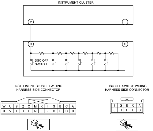
INSPECT DSC OFF SWITCH SIGNAL CIRCUIT FOR SHORT TO GROUND
•  Disconnect the DSC OFF switch.
•  Disconnect the instrument cluster connector.
•  Inspect for continuity between the DSC OFF switch connector terminal B (vehicle harness-side) and body ground.
•  Is there continuity?
Yes
Refer to the wiring diagram and verify whether or not there is a common connector between the DSC OFF switch connector terminal B (vehicle harness-side) and instrument cluster connector terminal V (vehicle harness-side).
If there is a common connector:
•  Determine the malfunctioning part by inspecting the common connector and the terminal for corrosion, damage, or pin disconnection, and the common wiring harness for a short to ground.
•  Repair or replace the malfunctioning part.
If there is no common connector:
•  Repair or replace the wiring harness which has a short to ground.
Go to Step 5.
No
Go to the next step.
3
INSPECT DSC OFF SWITCH SIGNAL CIRCUIT FOR OPEN CIRCUIT
•  Inspect for continuity between the DSC OFF switch connector terminal C (vehicle harness-side) and instrument cluster connector terminal T (vehicle harness-side).
•  Is there continuity?
Yes
Go to the next step.
No
Refer to the wiring diagram and verify whether or not there is a common connector between the DSC OFF switch connector terminal C (vehicle harness-side) and instrument cluster connector terminal T (vehicle harness-side).
If there is a common connector:
•  Determine the malfunctioning part by inspecting the common connector and the terminal for corrosion, damage, or pin disconnection, and the common wiring harness for an open circuit.
•  Repair or replace the malfunctioning part.
If there is no common connector:
•  Repair or replace the wiring harness which has an open circuit.
Go to Step 5.
4
INSPECT DSC OFF SWITCH
•  Inspect the DSC OFF switch.
•  Is the DSC OFF switch normal?
Yes
Go to the next step.
No
Replace the DSC OFF switch, then go to the next step.
5
VERIFY THAT THE SAME DTC IS NOT PRESENT
•  Reconnect all disconnected connectors.
•  Clear the DTCs from the memory.
•  Are the same DTCs present?
Yes
Repeat the inspection from Step 1.
No
Go to the next step.
6
VERIFY THAT NO OTHER DTCS ARE PRESENT
•  Are any other DTCs output?
Yes
Go to the applicable DTC inspection.
No
DTC troubleshooting completed.