Note
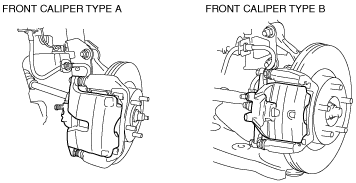
• Verify the shape of the caliper shown in the figure to determine type A or B.
am3zzw00015868
|
FRONT BRAKE (DISC) REMOVAL/INSTALLATION
id041100800900
am3zzw00015868
|
1. Remove in the order indicated in the table.
2. Install in the reverse order of removal.
3. After installation, add brake fluid, bleed the air, and inspect for fluid leakage. (See BRAKE FLUID AIR BLEEDING.)
4. Depress the brake pedal a few times, rotate the wheel by hand, and verify that the brake does not drag.
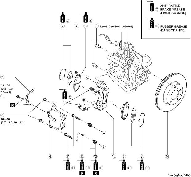
Front caliper type A
am3zzw00020481
|
|
1
|
Bolt
|
|
2
|
Brake hose
|
|
3
|
Bolt
|
|
4
|
Caliper
(See Disc Pad Installation Note.)
|
|
5
|
Disc pad
(See Disc Pad Installation Note.)
|
|
6
|
Wear indicator
|
|
7
|
Shim
|
|
8
|
Guide plate
|
|
9
|
Bolt
|
|
10
|
Mounting support
|
|
11
|
Slide pin
|
|
12
|
Bushing
|
|
13
|
Dust boot
|
|
14
|
Disc plate
|
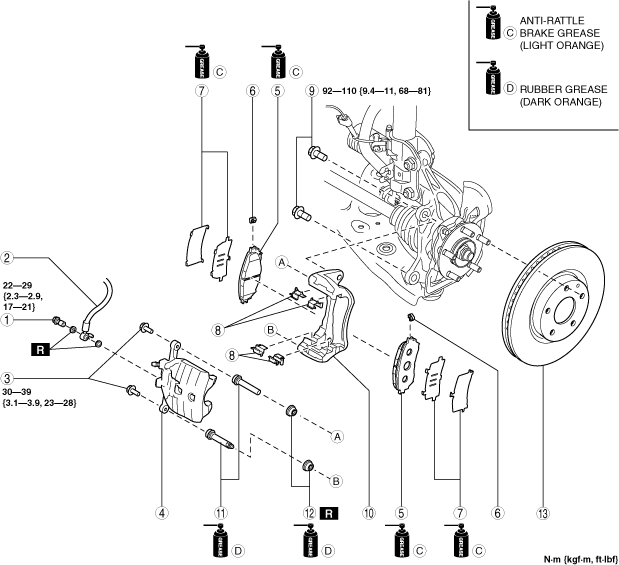
Front caliper type B
am3zzw00020482
|
|
1
|
Bolt
|
|
2
|
Brake hose
|
|
3
|
Bolt
|
|
4
|
Caliper
(See Disc Pad Installation Note.)
|
|
5
|
Disc pad
(See Disc Pad Installation Note.)
|
|
6
|
Wear indicator
|
|
7
|
Shim
|
|
8
|
Guide plate
|
|
9
|
Bolt
|
|
10
|
Mounting support
|
|
11
|
Slide pin
|
|
12
|
Dust boot
|
|
13
|
Disc plate
|
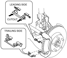
Guide Plate Installation Note (Front caliper type A only)
1. Install the guide plate as shown in the figure.
am3zzw00015869
|
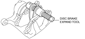
Disc Pad Installation Note
1. Clean the exposed area of the piston.
2. Push the piston in using the commercially available disc brake expand tool.
am3uuw00010880
|
3. Install the disc pads to the mounting support.