|
1
|
VERIFY RELATED SERVICE INFORMATION AVAILABILITY
• Verify related Service Information availability.
• Is any related Service Information available?
|
Yes
|
Perform repair or diagnosis according to the available Service Information.
• If the vehicle is not repaired, go to the next step.
|
|
No
|
Go to the next step.
|
|
2
|
INSPECT AT PUMP 15 A FUSE
• Switch the ignition off.
• Is the fuse blown?
|
Yes
|
Go to Step 6.
|
|
No
|
Go to the next step.
|
|
3
|
INSPECT ELECTRIC AT OIL PUMP RELAY
• Remove the electric AT oil pump relay.
• Inspect the electric AT oil pump relay.
• Is there any malfunction?
|
Yes
|
Replace the electric AT oil pump relay, then go to Step 10.
|
|
No
|
Go to the next step.
|
|
4
|
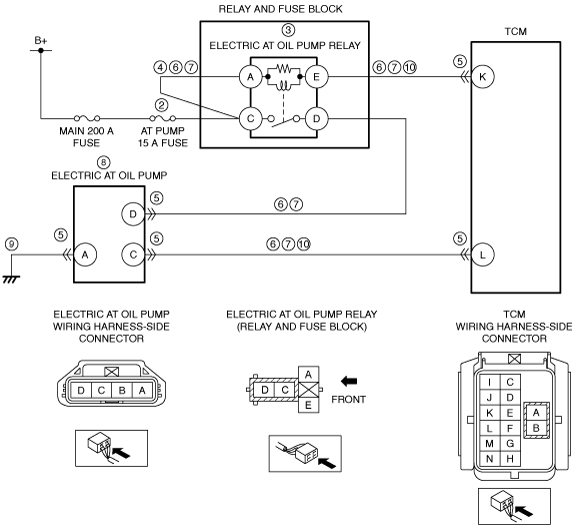
INSPECT ELECTRIC AT OIL PUMP RELAY POWER SUPPLY CIRCUIT FOR OPEN CIRCUIT
• Measure the voltage at the following terminals (wiring harness-side):
-
― Electric AT oil pump relay terminal A
― Electric AT oil pump relay terminal C
• Is the voltage 0 V?
|
Yes
|
Refer to the wiring diagram and verify whether or not there is a common connector between MAIN 200 A fuse and electric AT oil pump relay terminal C.
If there is a common connector:
• Determine the malfunctioning part by inspecting the common connector and the terminal for corrosion, damage, or pin disconnection, and the common wiring harness for an open circuit.
• Repair or replace the malfunctioning part.
If there is no common connector:
• Repair or replace the wiring harness which has an open circuit.
Go to Step 11.
|
|
No
|
Go to the next step.
|
|
5
|
INSPECT TCM AND ELECTRIC AT OIL PUMP CONNECTOR
• Disconnect the negative battery cable.
• Disconnect the following connectors.
-
― TCM
― Electric AT oil pump
• Visually inspect the engagement and connection condition of the connector, and terminals for damage, deformation, corrosion, or disconnection.
• Is there any malfunction?
|
Yes
|
Repair or replace the connector and/or terminals, then go to Step 11.
|
|
No
|
Go to the next step.
|
|
6
|
INSPECT ELECTRIC AT OIL PUMP RELAY CIRCUIT AND ELECTRIC AT OIL PUMP CIRCUIT FOR SHORT TO GROUND
• Verify that the electric AT oil pump relay, electric AT oil pump, and TCM connectors are disconnected.
• Inspect for continuity between the following terminals (wiring harness-side) and body ground:
-
― Electric AT oil pump relay terminal A—Electric AT oil pump relay terminal C
― Electric AT oil pump relay terminal D—Electric AT oil pump terminal D
― Electric AT oil pump relay terminal E—TCM terminal K
― Electric AT oil pump terminal C—TCM terminal L
• Is there continuity?
|
Yes
|
Refer to the wiring diagram and verify whether or not there is a common connector between the following terminals:
• Electric AT oil pump relay terminal A—Electric AT oil pump relay terminal C
• Electric AT oil pump relay terminal D—Electric AT oil pump terminal D
• Electric AT oil pump relay terminal E—TCM terminal K
• Electric AT oil pump terminal C—TCM terminal L
If there is a common connector:
• Determine the malfunctioning part by inspecting the common connector and the terminal for corrosion, damage, or pin disconnection, and the common wiring harness for a short to ground.
• Repair or replace the malfunctioning part.
If there is no common connector:
• Repair or replace the wiring harness which has a short to ground.
Go to Step 11.
|
|
No
|
Go to the next step.
|
|
7
|
INSPECT ELECTRIC AT OIL PUMP RELAY CIRCUIT AND ELECTRIC AT OIL PUMP CIRCUIT FOR OPEN CIRCUIT
• Verify that the electric AT oil pump relay, electric AT oil pump, and TCM connectors are disconnected.
• Inspect for continuity between the following terminals (wiring harness-side):
-
― Electric AT oil pump relay terminal A—Electric AT oil pump relay terminal C
― Electric AT oil pump relay terminal D—Electric AT oil pump terminal D
― Electric AT oil pump relay terminal E—TCM terminal K
― Electric AT oil pump terminal C—TCM terminal L
• Is there continuity?
|
Yes
|
Go to the next step.
|
|
No
|
Refer to the wiring diagram and verify whether or not there is a common connector between the following terminals:
• Electric AT oil pump relay terminal A—Electric AT oil pump relay terminal C
• Electric AT oil pump relay terminal D—Electric AT oil pump terminal D
• Electric AT oil pump relay terminal E—TCM terminal K
• Electric AT oil pump terminal C—TCM terminal L
If there is a common connector:
• Determine the malfunctioning part by inspecting the common connector and the terminal for corrosion, damage, or pin disconnection, and the common wiring harness for an open circuit.
• Repair or replace the malfunctioning part.
If there is no common connector:
• Repair or replace the wiring harness which has an open circuit.
Go to Step 11.
|
|
8
|
INSPECT ELECTRIC AT OIL PUMP
• Remove the electric AT oil pump.
• Verify that the resistance according to the following:
-
― Between electric AT oil pump terminal D and A: Approx. 18.2 Kilohms
― Between electric AT oil pump terminal C and A: Approx. 21.5 Kilohms
• Is the resistance normal?
|
Yes
|
Install the electric AT oil pump, then go to the next step.
|
|
No
|
Replace the electric AT oil pump, then go to Step 11.
|
|
9
|
INSPECT ELECTRIC AT OIL PUMP GROUND CIRCUIT FOR OPEN CIRCUIT
• Verify that the electric AT oil pump relay, electric AT oil pump, and TCM connectors are disconnected.
• Inspect for continuity between electric AT oil pump terminal A (wiring harness-side) and body ground.
• Is there continuity?
|
Yes
|
Go to the next step.
|
|
No
|
Refer to the wiring diagram and verify whether or not there is a common connector between electric AT oil pump terminal A and body ground.
If there is a common connector:
• Determine the malfunctioning part by inspecting the common connector and the terminal for corrosion, damage, or pin disconnection, and the common wiring harness for an open circuit.
• Repair or replace the malfunctioning part.
If there is no common connector:
• Repair or replace the wiring harness which has an open circuit.
Go to Step 11.
|
|
10
|
INSPECT ELECTRIC AT OIL PUMP CIRCUIT FOR SHORT TO POWER SUPPLY
• Verify that the electric AT oil pump relay, electric AT oil pump, and TCM connectors are disconnected.
• Reconnect the negative battery cable.
• Switch the ignition ON (engine on).
• Measure the voltage at the following terminals (wiring harness-side):
-
― TCM terminal K
― TCM terminal L
• Is the voltage 0 V?
|
Yes
|
Go to the next step.
|
|
No
|
Refer to the wiring diagram and verify whether or not there is a common connector between the following terminals:
• TCM terminal K—Electric AT oil pump relay terminal E
• TCM terminal L—Electric AT oil pump terminal C
If there is a common connector:
• Determine the malfunctioning part by inspecting the common connector and the terminal for corrosion, damage, or pin disconnection, and the common wiring harness for a short to power supply.
• Repair or replace the malfunctioning part.
If there is no common connector:
• Repair or replace the wiring harness which has a short to power supply.
Go to the next step.
|
|
11
|
VERIFY DTC TROUBLESHOOTING COMPLETED
• Always reconnect all disconnected connectors.
• Replace the fuse if it is blown.
• Reconnect the negative battery cable.
• Clear the DTC using the M-MDS.
• Perform the following procedure to ensure that the DTC has been resolved:
-
1. Operate i-stop for 10 s or more.
• Perform the DTC inspection using the M-MDS.
• Are any DTCs present?
|
Yes
|
Go to the applicable DTC inspection.
|
|
No
|
DTC troubleshooting completed.
|