 |
am6zzw00009023
MECHANICAL SYSTEM TEST [CW6A-EL]
id0517l1118300
Mechanical System Test Preparation
1. Apply the parking brake firmly, and set the wheel blocks for both the front and rear wheels.
2. Inspect the engine coolant level. (See ENGINE COOLANT LEVEL INSPECTION [SKYACTIV-G 1.5, SKYACTIV-G 2.0, SKYACTIV-G 2.5].)
3. Inspect the engine oil level. (See ENGINE OIL LEVEL INSPECTION [SKYACTIV-G 1.5, SKYACTIV-G 2.0, SKYACTIV-G 2.5].)
4. Inspect the ATF level. (See AUTOMATIC TRANSAXLE FLUID (ATF) INSPECTION [CW6A-EL].)
5. Inspect the ignition timing. (See ENGINE TUNE-UP [SKYACTIV-G 1.5, SKYACTIV-G 2.0, SKYACTIV-G 2.5].)
6. Inspect the idle speed. (See ENGINE TUNE-UP [SKYACTIV-G 1.5, SKYACTIV-G 2.0, SKYACTIV-G 2.5].)
7. Verify that no DTCs are stored.
Line Pressure Test
1. Perform the mechanical system test preparation. (See Mechanical System Test Preparation.)
2. Remove the front under cover No.2. (See FRONT UNDER COVER No.2 REMOVAL/INSTALLATION.)
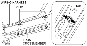
3. Disconnect the wiring harness from the front crossmember. (Vehicle with i-ELOOP)
am6zzw00009023
|
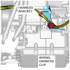
4. Disconnect the wiring harness clip from the harness bracket.
am2zzw00009381
|
5. Remove the splash shield. (LH) (See SPLASH SHIELD REMOVAL/INSTALLATION.)
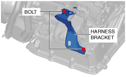
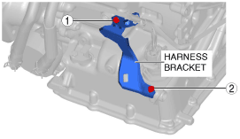
6. Remove the harness bracket installation bolts from the transaxle and set it aside.
am2zzw00009382
|
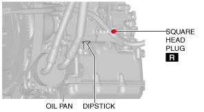
7. Remove the pressure detection square head plug.
am2zzw00009383
|
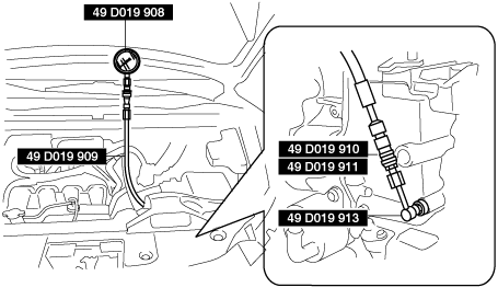
8. Install SSTs (49 D019 908, 49 D019 909, 49 D019 910, 49 D019 911, 49 D019 913) to the line pressure detection port as shown in the figure.
ac5wzw00002429
|
9. Start the engine.
10. Warm up the engine until the ATF temperature is 60—70 °C {140—158 °F}.
11. Shift the selector lever to the D position.
12. Measure the line pressure while idling in D position.
13. Measure the line pressures while idling in the M (1st gear) and R positions using the same procedure.
14. Stop the engine.
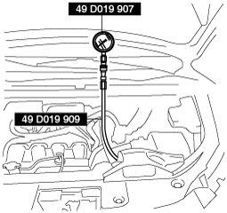
15. Change the low-pressure gauge (49 D019 908) to the high-pressure gauge (49 D019 907).
adejjw00011843
|
16. Start the engine.
17. Measure the line pressure while stalling in D position.
18. Measure the line pressure while stalling for positions other than D in the same procedure.
|
Condition |
Possible cause |
|
|---|---|---|
|
Lower than specification
|
Lower in R, D, and M (1GR) position
|
• Oil pump wear
• ATF leakage from oil pump, control valve body, and transaxle case
• Pressure regulator valve sticking
• Pressure control solenoid malfunction
• Solenoid reducing valve sticking
|
|
Lower in D and M (1GR) position
|
• ATF leakage from low clutch hydraulic circuit
|
|
|
Lower in R and M (1GR) position
|
• ATF leakage from low and reverse brake hydraulic circuit
|
|
|
Lower in R position
|
• ATF leakage from R-3-5 brake hydraulic circuit
|
|
|
Higher than specification
|
Higher in R, D, and M (1GR) position
|
• Pressure regulator valve sticking
• Pressure control solenoid malfunction
|
Line pressure
|
Measurement conditions |
Specification (kPa {kgf/cm2, psi}) |
|
|---|---|---|
|
Idling
|
R position
|
500—700 {5.10—7.13, 72.6—101.0}
|
|
D and M (1GR) position
|
330—470 {3.37—4.79, 47.9—68.1}
|
|
|
Stalling
|
R position
|
1,790—2,100 {18.26—21.41, 259.7—304.5}
|
|
D and M (1GR) position
|
970—1,170 {9.90—11.93, 141.0—169.6}
|
|
19. Stop the engine.
20. Remove the SSTs.
21. Install a new square head plug.
am2zzw00009383
|
22. Tighten the harness bracket installation bolts in the order shown in the figure.
am2zzw00009384
|
23. Install the splash shield. (LH) (See SPLASH SHIELD REMOVAL/INSTALLATION.)
24. Connect the wiring harness clip to the harness bracket.
am2zzw00009381
|
25. Connect the wiring harness to the front crossmember. (Vehicle with i-ELOOP)
am6zzw00009023
|
26. Install the front under cover No.2. (See FRONT UNDER COVER No.2 REMOVAL/INSTALLATION.)
Stall Test
1. Perform the mechanical system test preparation. (See Mechanical System Test Preparation.)
2. Apply the parking brake firmly, and set the wheel blocks for both the front and rear wheels.
3. Start the engine.
4. Measure the stall speed in the D position.
5. Measure the stall speed in the M (1st gear) and R positions using the same procedure.
|
Condition |
Possible cause |
||
|---|---|---|---|
|
Higher than specification
|
Higher in R, D, and M (1GR) position
|
Line pressure is low
|
• Oil pump wear
• ATF leakage from oil pump, control valve body, and transaxle case
• Pressure regulator valve sticking
• TR control valve sticking
• Pressure control solenoid operation malfunction
|
|
• Low and reverse brake slippage
|
|||
|
Higher in D and M (1GR) position
|
• Low clutch slippage
|
||
|
Higher in R position
|
Perform road test to determine whether problem is in R-3-5 brake or low and reverse brake
• Engine brake operates in M (1GR) position
• Engine braking does not operate in M (1GR) position
|
||
|
Lower than specification
|
Lower in R, D, and M (1GR) position
|
• Engine malfunction
• One-way clutch slippage in torque converter
|
|
Stall speed
|
Measurement conditions |
Standard value (rpm) |
|---|---|
|
R position
|
1,800—2,400
|
|
D position
|
2,500—3,400
|
|
M position
|
Time Lag Test
1. Perform the mechanical system test preparation. (See Mechanical System Test Preparation.)
2. Apply the parking brake firmly, and set the wheel blocks for both the front and rear wheels.
3. Start the engine.
4. Measure the time lag from the N position to the D position.
5. Measure the time lag from the N position to the R position using the same procedure.
|
Condition |
Possible cause |
|
|---|---|---|
|
N to D selected
|
Longer than specification
|
• Line pressure is low
• Low clutch slippage
• ATF leakage from low clutch hydraulic circuit
• ATF leakage from low and reverse brake hydraulic circuit
• Shift solenoid No.1 operation malfunction
• Shift solenoid No.4 operation malfunction
|
|
Shorter than specification
|
• Line pressure is high
• N-D accumulator operation malfunction
• Shift solenoid No.1 operation malfunction
• Shift solenoid No.4 operation malfunction
|
|
|
N to R selected
|
Longer than specification
|
• Line pressure is low
• Low and Reverse brake slippage
• R-3-5 brake slippage
• ATF leakage from R-3-5 brake hydraulic circuit
• ATF leakage from low and reverse brake hydraulic circuit
• Shift solenoid No.3 operation malfunction
• Shift solenoid No.4 operation malfunction
|
|
Shorter than specification
|
• Line pressure is high
• N-R accumulator operation malfunction
• Shift solenoid No.3 operation malfunction
• Shift solenoid No.4 operation malfunction
|
|
Time lag
|
Measurement conditions |
Specification (s) |
|---|---|
|
N to D selected
|
0.4—0.7
|
|
N to R selected
|