|
1
|
INSPECT FRONT COMBINATION LIGHT (LH) CONNECTOR CONDITION
• Switch the ignition to off.
• Disconnect the negative battery cable.
• Disconnect the front combination light (LH) connector.
• Inspect the connector engagement and connection condition and inspect the terminals for damage, deformation, corrosion, or disconnection.
• Is the connector normal?
|
Yes
|
Go to the next step.
|
|
No
|
Repair or replace the connector, then go to Step 8.
|
|
2
|
INSPECT FRONT COMBINATION LIGHT (RH) CONNECTOR CONDITION
• Disconnect the front combination light (RH) connector.
• Inspect the connector engagement and connection condition and inspect the terminals for damage, deformation, corrosion, or disconnection.
• Is the connector normal?
|
Yes
|
Go to the next step.
|
|
No
|
Repair or replace the connector, then go to Step 8.
|
|
3
|
INSPECT ADAPTIVE FRONT LIGHTING SYSTEM (AFS) CONTROL MODULE CONNECTOR CONDITION
• Disconnect the adaptive front lighting system (AFS) control module connector.
• Inspect the connector engagement and connection condition and inspect the terminals for damage, deformation, corrosion, or disconnection.
• Is the connector normal?
|
Yes
|
Go to the next step.
|
|
No
|
Repair or replace the connector, then go to Step 8.
|
|
4
|
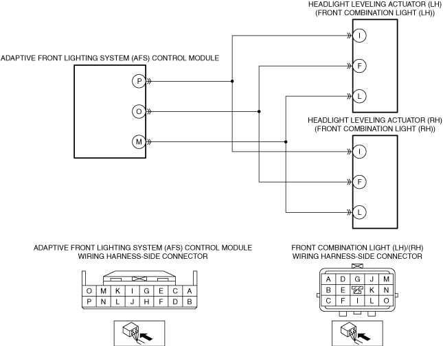
INSPECT HEADLIGHT LEVELING ACTUATOR CIRCUIT FOR SHORT TO GROUND
• Verify that the front combination light (LH), front combination light (RH) and adaptive front lighting system (AFS) control module connectors are disconnected.
• Inspect for continuity between the following terminals (wiring harness-side) and body ground:
-
― Front combination light (LH) terminal I
― Front combination light (LH) terminal F
― Front combination light (RH) terminal I
― Front combination light (RH) terminal F
• Is there continuity?
|
Yes
|
Refer to the wiring diagram and verify whether or not there is a common connector between the following terminals:
• Adaptive front lighting system (AFS) control module terminal P—Front combination light (LH) terminal I
• Adaptive front lighting system (AFS) control module terminal O—Front combination light (LH) terminal F
• Adaptive front lighting system (AFS) control module terminal P—Front combination light (RH) terminal I
• Adaptive front lighting system (AFS) control module terminal O—Front combination light (RH) terminal F
If there is a common connector:
• Determine the malfunctioning part by inspecting the common connector and the terminal for corrosion, damage, or pin disconnection, and the common wiring harness for a short to ground.
• Repair or replace the malfunctioning part.
If there is no common connector:
• Repair or replace the wiring harness which has a short to ground.
Go to Step 8.
|
|
No
|
Go to the next step.
|
|
5
|
INSPECT HEADLIGHT LEVELING ACTUATOR CIRCUIT FOR OPEN CIRCUIT
• Verify that the front combination light (LH), front combination light (RH) and adaptive front lighting system (AFS) control module connectors are disconnected.
• Inspect for continuity between the following terminals (wiring harness-side):
-
― Adaptive front lighting system (AFS) control module terminal P—Front combination light (LH) terminal I
― Adaptive front lighting system (AFS) control module terminal O—Front combination light (LH) terminal F
― Adaptive front lighting system (AFS) control module terminal P—Front combination light (RH) terminal I
― Adaptive front lighting system (AFS) control module terminal O—Front combination light (RH) terminal F
• Is there continuity?
|
Yes
|
Go to the next step.
|
|
No
|
Refer to the wiring diagram and verify whether or not there is a common connector between the following terminals:
• Adaptive front lighting system (AFS) control module terminal P—Front combination light (LH) terminal I
• Adaptive front lighting system (AFS) control module terminal O—Front combination light (LH) terminal F
• Adaptive front lighting system (AFS) control module terminal P—Front combination light (RH) terminal I
• Adaptive front lighting system (AFS) control module terminal O—Front combination light (RH) terminal F
If there is a common connector:
• Determine the malfunctioning part by inspecting the common connector and the terminal for corrosion, damage, or pin disconnection, and the common wiring harness for an open circuit.
• Repair or replace the malfunctioning part.
If there is no common connector:
• Repair or replace the wiring harness which has an open circuit.
Go to Step 8.
|
|
6
|
INSPECT HEADLIGHT LEVELING ACTUATOR (LH) OPERATION
• Perform the headlight leveling actuator (LH) operation check mode.
• Does the headlight leveling actuator (LH) operate normally?
|
Yes
|
Go to the next step.
|
|
No
|
Replace the front combination light (LH), then go to Step 8.
|
|
7
|
INSPECT HEADLIGHT LEVELING ACTUATOR (RH) OPERATION
• Perform the headlight leveling actuator (RH) operation check mode.
• Does the headlight leveling actuator (RH) operate normally?
|
Yes
|
Go to the next step.
|
|
No
|
Replace the front combination light (RH), then go to the next step.
|
|
8
|
VERIFY THAT REPAIRS HAVE BEEN COMPLETED
• Always reconnect all disconnected connectors.
• Connect the negative battery cable.
• Clear the adaptive front lighting system (AFS) control module DTCs using the M-MDS.
• Switch the ignition ON (engine off or on) and wait for 5 s or more.
• Retrieve the adaptive front lighting system (AFS) control module DTCs using the M-MDS.
• Is the same DTC displayed?
|
Yes
|
Repeat the inspection from Step 1.
• If the malfunction recurs, replace the adaptive front lighting system (AFS) control module, then go to the next step.
|
|
No
|
Go to the next step.
|
|
9
|
VERIFY IF OTHER DTCs DISPLAYED
• Are any other DTCs displayed?
|
Yes
|
Repair the malfunctioning part according to the applicable DTC troubleshooting.
|
|
No
|
DTC troubleshooting completed.
|