DTC B116A:12 [CONNECTIVITY MASTER UNIT]


id0902n7103700

Description

Microphone circuit malfunction

Detection condition
•  The connectivity master unit (CMU) detected a short to power supply in the microphone circuit for 5 s or more with the ignition switched ON (engine off or on).
Fail-safe function
Not applicable
Possible cause
•  Microphone connector or terminal malfunction
•  Connectivity master unit (CMU) connector or terminal malfunction
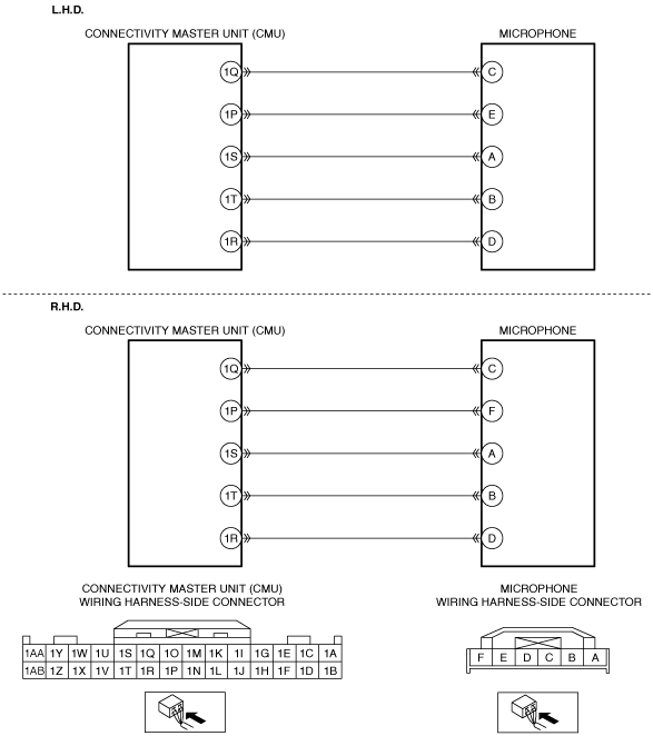
•  Short to power supply in wiring harness between the following terminals:
―  Connectivity master unit (CMU) terminal 1S and microphone terminal A
―  Connectivity master unit (CMU) terminal 1T and microphone terminal B
•  Microphone malfunction
•  Connectivity master unit (CMU) malfunction

Diagnostic Procedure

Step

Inspection

Action

1
INSPECT MICROPHONE CONNECTOR CONDITION
•  Switch the ignition off.
•  Disconnect the microphone connector.
•  Inspect the connector engagement and connection condition and inspect the terminals for damage, deformation, corrosion, or disconnection.
•  Is the connector normal?
Yes
Go to the next step.
No
Repair or replace the connector, then go to Step 5.
2
INSPECT CONNECTIVITY MASTER UNIT (CMU) CONNECTOR CONDITION
•  Disconnect the connectivity master unit (CMU) connector.
•  Inspect the connector engagement and connection condition and inspect the terminals for damage, deformation, corrosion, or disconnection.
•  Is the connector normal?
Yes
Go to the next step.
No
Repair or replace the connector, then go to Step 5.
3
INSPECT MICROPHONE CIRCUIT FOR SHORT TO POWER SUPPLY
•  Verify that the microphone and connectivity master unit (CMU) connectors are disconnected.
•  Switch the ignition ON (engine off or on).
•  Measure the voltage at the following terminals (wiring harness-side).
―  Microphone terminal A
―  Microphone terminal B
•  Is the voltage 0 V?
Yes
Go to the next step.
No
Refer to the wiring diagram and verify if there is a common connector between the following terminals.
•  Connectivity master unit (CMU) terminal 1S and microphone terminal A
•  Connectivity master unit (CMU) terminal 1T and microphone terminal B
If there is a common connector:
•  Inspect the common connector and terminals for corrosion, damage, or disconnection and the common wiring harnesses for short to power supply to determine the malfunctioning location.
•  Repair or replace the malfunctioning location.
If there is no common connector:
•  Repair or replace the wiring harness which is shorted to the power supply.
Go to Step 5.
4
PERFORM DTC INSPECTION AND VERIFY IF MALFUNCTIONING LOCATION IS MICROPHONE
•  Always reconnect all disconnected connectors.
•  Clear the DTC for the connectivity master unit (CMU) using the M-MDS.
•  Switch the ignition ON (engine off or on) and wait for 12 s or more.
•  Perform the DTC inspection for the connectivity master unit (CMU) using the M-MDS.
•  Is the same DTC displayed?
Yes
Replace the microphone, then go to the next step.
No
Go to Step 6.
5
VERIFY THAT REPAIRS HAVE BEEN COMPLETED
•  Always reconnect all disconnected connectors.
•  Clear the DTC for the connectivity master unit (CMU) using the M-MDS.
•  Switch the ignition ON (engine off or on) and wait for 12 s or more.
•  Perform the DTC inspection for the connectivity master unit (CMU) using the M-MDS.
•  Is the same DTC displayed?
Yes
Repeat the inspection from Step 1.
•  If the malfunction recurs, replace the connectivity master unit (CMU).
Go to the next step.
No
Go to the next step.
6
VERIFY IF OTHER DTCs DISPLAYED
•  Are any other DTCs displayed?
Yes
Repair the malfunctioning location according to the applicable DTC troubleshooting.
No
DTC troubleshooting completed.