FOREWORD [REAR VEHICLE MONITORING SYSTEM]
id0903z7378400
• When the system component parts are replaced/removed/installed, the rear vehicle monitoring configuration and rear vehicle monitoring radar aiming for the radar sensor must be performed. Perform the relevant initial setting servicing referring to the corresponding removal/installation procedure.
• The rear vehicle monitoring system is a control device which monitors the vehicle's rear for approaching vehicles using radio waves emitted from the radar sensor which reflect off the detected vehicle and return to the radio sensor part of the control module. The rear vehicle monitoring system may not operate normally under the following conditions:
Effects of weather conditions
-
― Vehicle is driven in rain, snow, or fog.
Effects of driving conditions
-
― Vehicle does not approach even though the vehicle enters the detection area from the rear of the detecting vehicle
― Vehicles which are traveling at nearly the same speed as the detecting vehicle for long periods
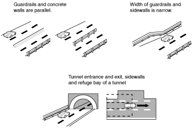
― Vehicles in an adjacent lane on a road with a wider lane width (detection area for radar sensor is set for highway width)
Effects of vehicle equipment conditions
-
― Rear bumper around radar sensor is deformed.
― Ice, snow or dirt is adhering to the rear bumper radar sensors.
Effects of vehicle approaching from the rear
-
― Small motorcycle
― Vehicles with body shapes that may not reflect radar (unloaded trailers with low vehicle height, sports cars)
Effects of road conditions
-
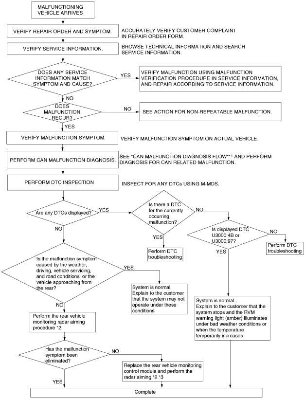
Troubleshooting Procedure
Action for non-repeatable malfunction
• If the malfunction does not recur, verify the malfunction cause by performing the following actions:
-
― Based on the repair order form, attempt to drive the vehicle or perform tests to replicate the malfunction, record the data at that time, and detect the malfunction cause.
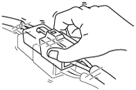
― Refer to [Determining Open Circuit Location] based on the recorded DTC, shake the wiring harness or connector of the electrical component which is suspected to be the cause of the malfunction, and inspect for any changes in CAN system voltage or occurrence of any DTCs.
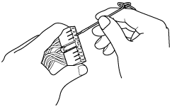
― Inspect the female terminals on the connector of the electric component which is suspected to be the cause of the malfunction for poor connection.