 |
ac5wzw00001248
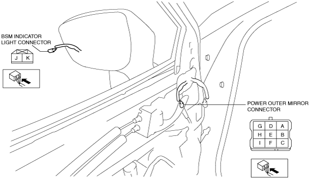
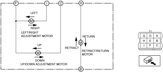
POWER OUTER MIRROR INSPECTION
id091200002700
Mirror Glass Adjustment
1. Disconnect the negative battery cable. (See NEGATIVE BATTERY CABLE DISCONNECTION/CONNECTION [MZR 1.6].) (See NEGATIVE BATTERY CABLE DISCONNECTION/CONNECTION [SKYACTIV-G 1.5, SKYACTIV-G 2.0, SKYACTIV-G 2.5].) (See NEGATIVE BATTERY CABLE DISCONNECTION/CONNECTION [SKYACTIV-D 2.2].)(See NEGATIVE BATTERY CABLE DISCONNECTION/CONNECTION [SKYACTIV-D 1.5].)
2. Remove the following parts:
3. Apply battery positive voltage and connect the ground to the power outer mirror terminals and inspect the power outer mirror operation.
|
Operation |
B+ terminal |
Ground terminal |
|---|---|---|
|
Up
|
C
|
F
|
|
Down
|
F
|
C
|
|
Left
|
I
|
F
|
|
Right
|
F
|
I
|
|
Retract
|
B
|
H
|
|
Return
|
H
|
B
|
ac5wzw00001248
|
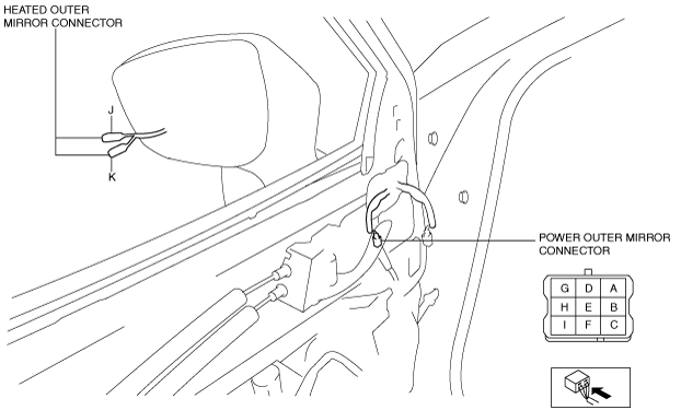
Heated Outer Mirror Inspection
1. Disconnect the negative battery cable. (See NEGATIVE BATTERY CABLE DISCONNECTION/CONNECTION [MZR 1.6].) (See NEGATIVE BATTERY CABLE DISCONNECTION/CONNECTION [SKYACTIV-G 1.5, SKYACTIV-G 2.0, SKYACTIV-G 2.5].) (See NEGATIVE BATTERY CABLE DISCONNECTION/CONNECTION [SKYACTIV-D 2.2].)(See NEGATIVE BATTERY CABLE DISCONNECTION/CONNECTION [SKYACTIV-D 1.5].)
2. Remove the following parts:
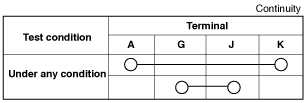
3. Verify that the continuity between heated outer mirror connector terminals is as indicated in the table.
am6zzw00011647
|
am6zzw00011646
|
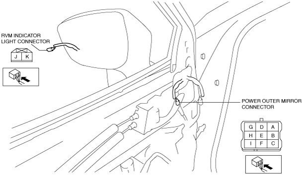
RVM Indicator Light Inspection
1. Disconnect the negative battery cable. (See NEGATIVE BATTERY CABLE DISCONNECTION/CONNECTION [MZR 1.6].) (See NEGATIVE BATTERY CABLE DISCONNECTION/CONNECTION [SKYACTIV-G 1.5, SKYACTIV-G 2.0, SKYACTIV-G 2.5].) (See NEGATIVE BATTERY CABLE DISCONNECTION/CONNECTION [SKYACTIV-D 2.2].)(See NEGATIVE BATTERY CABLE DISCONNECTION/CONNECTION [SKYACTIV-D 1.5].)
2. Remove the following parts:
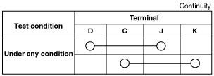
3. Verify that the continuity between RVM indicator light connector terminals is as indicated in the table.
am3zzw00017740
|
am3zzw00017741
|
BSM Indicator Light Inspection
1. Disconnect the negative battery cable. (See NEGATIVE BATTERY CABLE DISCONNECTION/CONNECTION [MZR 1.6].) (See NEGATIVE BATTERY CABLE DISCONNECTION/CONNECTION [SKYACTIV-G 1.5, SKYACTIV-G 2.0, SKYACTIV-G 2.5].) (See NEGATIVE BATTERY CABLE DISCONNECTION/CONNECTION [SKYACTIV-D 2.2].)(See NEGATIVE BATTERY CABLE DISCONNECTION/CONNECTION [SKYACTIV-D 1.5].)
2. Remove the following parts:
3. Verify that the continuity between BSM indicator light connector terminals is as indicated in the table.
am3zzw00014258
|
am6zzw00011640
|