 |
am3uuw00011411
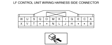
LF CONTROL UNIT INSPECTION
id091400110600
1. Remove the service hole cover on the front side trim. (See LF CONTROL UNIT REMOVAL/INSTALLATION.)
2. Verify that the voltages of each of the terminals are as indicated in the terminal voltage table (reference).
Terminal Voltage Table (Reference)
am3uuw00011411
|
|
Terminal |
Signal name |
Connected to |
Measurement conditions |
Voltage (V) |
Inspection item (s) |
|||
|---|---|---|---|---|---|---|---|---|
|
A
|
Request switch signal (RF)
|
Request switch (RF)
|
When request switch (RF) is pressed
|
1.0 or less
|
• Front outer handle (RH)
• Related wiring harness
|
|||
|
When request switch (RF) is not pressed
|
5.0
|
|||||||
|
B
|
Power supply
|
ROOM 15 A fuse
|
Under any condition
|
B+
|
• ROOM 15 A fuse
• Battery
• Related wiring harness
|
|||
|
C
|
Request switch signal (LF)
|
Request switch (LF)
|
When request switch (LF) is pressed
|
1.0 or less
|
• Front outer handle (LH)
• Related wiring harness
|
|||
|
When request switch (LF) is not pressed
|
5.0
|
|||||||
|
E
|
Request switch signal (liftgate)
|
Request switch (Liftgate)
|
When liftgate request switch is pressed
|
1.0 or less
|
• Request switch (Liftgate)
• Related wiring harness
|
|||
|
When liftgate request switch is not pressed
|
5.0
|
|||||||
|
G
|
Start stop unit signal
|
Start stop unit
|
Because this terminal is for communication, integrity determination using terminal voltage inspection is not possible.
|
|||||
|
H
|
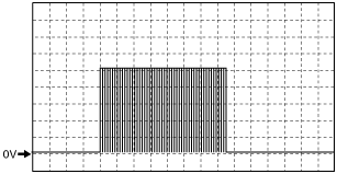
Keyless beeper power supply
|
Keyless beeper
|
When lock button on remote transmitter is pressed
|
Wave pattern (See Pattern 1.)
|
• Related wiring harness
• Keyless beeper
|
|||
|
Except above
|
1.0 or less
|
|||||||
|
I
|
Start stop unit signal
|
Start stop unit
|
Because this terminal is for communication, integrity determination using terminal voltage inspection is not possible.
|
|||||
|
J
|
GROUND
|
Keyless beeper
|
Under any condition
|
1.0 or less
|
• Related wiring harness
• Keyless beeper
|
|||
|
K
|
Keyless antenna (interior, front)
|
Keyless antenna (interior, front)
|
Because this terminal is for communication, integrity determination using terminal voltage inspection is not possible.
|
|||||
|
L
|
GROUND
|
Body ground
|
Under any condition
|
1.0 or less
|
Body ground
|
|||
|
M
|
Keyless antenna (interior, front)
|
Keyless antenna (interior, front)
|
Because this terminal is for communication, integrity determination using terminal voltage inspection is not possible.
|
|||||
|
N
|
GROUND
|
Shield ground
|
Under any condition
|
1.0 or less
|
Body ground
|
|||
|
O
|
Keyless antenna (exterior, LF)
|
Keyless antenna (exterior, LF)
|
Because this terminal is for communication, integrity determination using terminal voltage inspection is not possible.
|
|||||
|
Q
|
Keyless antenna (exterior, LF)
|
Keyless antenna (exterior, LF)
|
Because this terminal is for communication, integrity determination using terminal voltage inspection is not possible.
|
|||||
|
S
|
Keyless antenna (exterior, RF)
|
Keyless antenna (exterior, RF)
|
Because this terminal is for communication, integrity determination using terminal voltage inspection is not possible.
|
|||||
|
T
|
Keyless antenna (interior, rear)
|
Keyless antenna (interior, rear)
|
Because this terminal is for communication, integrity determination using terminal voltage inspection is not possible.
|
|||||
|
U
|
Keyless antenna (exterior, RF)
|
Keyless antenna (exterior, RF)
|
Because this terminal is for communication, integrity determination using terminal voltage inspection is not possible.
|
|||||
|
V
|
Keyless antenna (interior, rear)
|
Keyless antenna (interior, rear)
|
Because this terminal is for communication, integrity determination using terminal voltage inspection is not possible.
|
|||||
|
W
|
Keyless antenna (exterior, rear)
|
Keyless antenna (exterior, rear)
|
Because this terminal is for communication, integrity determination using terminal voltage inspection is not possible.
|
|||||
|
X
|
Keyless antenna (exterior, rear)
|
Keyless antenna (exterior, rear)
|
Because this terminal is for communication, integrity determination using terminal voltage inspection is not possible.
|
|||||
Inspection Using an Oscilloscope (Reference)
Pattern 1
ac5jjw00000788
|