 |
am3uuw00011343
BLIND SPOT MONITORING (BSM) CONTROL MODULE REMOVAL/INSTALLATION
id092200013600
4SD
1. Disconnect the negative battery cable. (See NEGATIVE BATTERY CABLE DISCONNECTION/CONNECTION [SKYACTIV-G 1.5, SKYACTIV-G 2.0, SKYACTIV-G 2.5].) (See NEGATIVE BATTERY CABLE DISCONNECTION/CONNECTION [SKYACTIV-D 2.2].)(See NEGATIVE BATTERY CABLE DISCONNECTION/CONNECTION [SKYACTIV-D 1.5].)
2. Remove the rear combination light. (See REAR COMBINATION LIGHT REMOVAL/INSTALLATION.)
3. Remove the rear bumper. (See REAR BUMPER REMOVAL/INSTALLATION.)
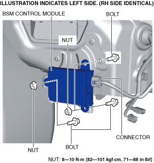
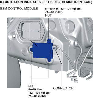
4. Disconnect the connector.
am3uuw00011343
|
5. Remove the nuts.
6. Remove the BSM control module.
7. Install in the reverse order of removal.
8. Perform the BSM radar test. (See BLIND SPOT MONITORING (BSM) RADAR TEST.)
5HB
1. Disconnect the negative battery cable. (See NEGATIVE BATTERY CABLE DISCONNECTION/CONNECTION [SKYACTIV-G 1.5, SKYACTIV-G 2.0, SKYACTIV-G 2.5].) (See NEGATIVE BATTERY CABLE DISCONNECTION/CONNECTION [SKYACTIV-D 2.2].)(See NEGATIVE BATTERY CABLE DISCONNECTION/CONNECTION [SKYACTIV-D 1.5].)
2. Remove the rear combination light. (See REAR COMBINATION LIGHT REMOVAL/INSTALLATION.)
3. Remove the rear bumper. (See REAR BUMPER REMOVAL/INSTALLATION.)
4. Disconnect the connector.
am3uuw00012272
|
5. Remove the nuts.
6. Remove the bolts.
7. Remove the BSM control module.
8. Install in the reverse order of removal.
9. Perform the BSM radar test. (See BLIND SPOT MONITORING (BSM) RADAR TEST.)