 |
am3zzw00017861
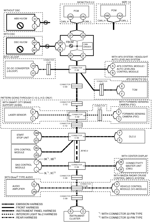
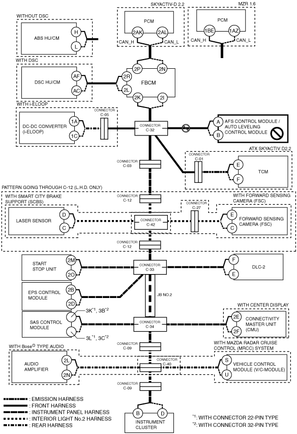
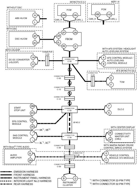
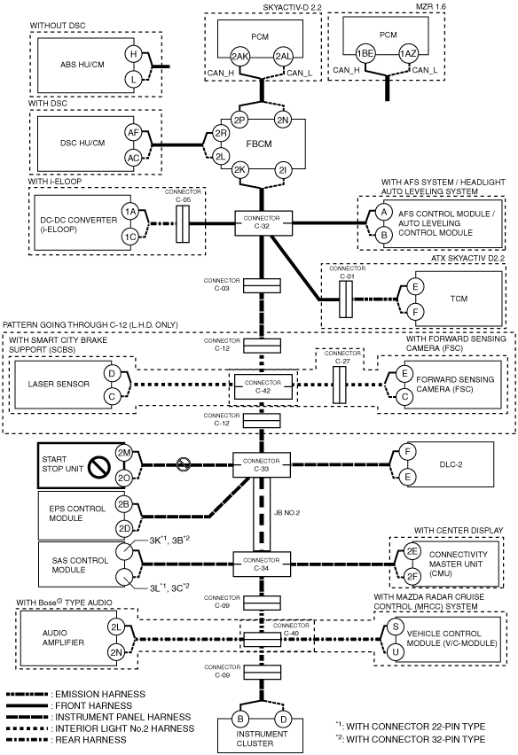
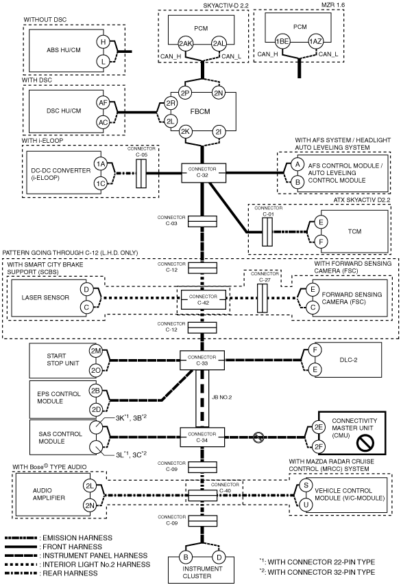
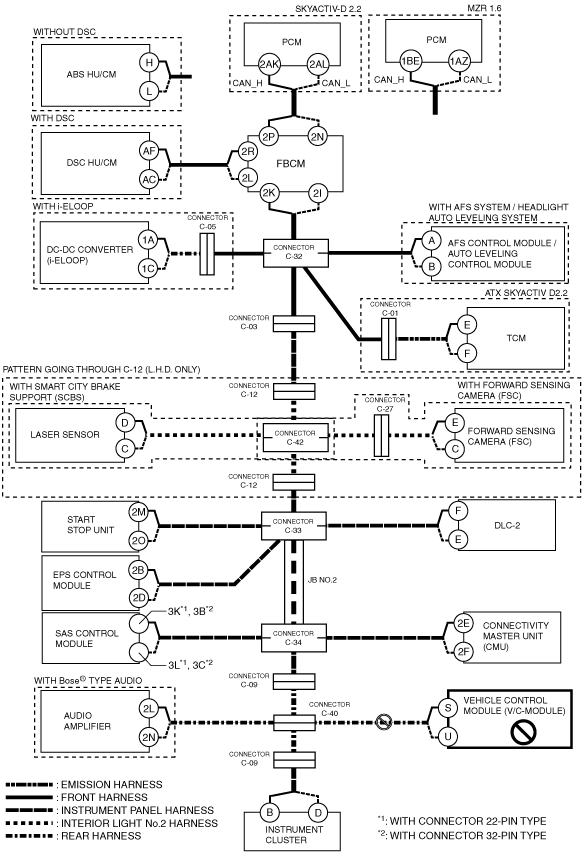
DETERMINING OPEN CIRCUIT LOCATION (HS-CAN) [SKYACTIV-D 2.2 (ATX), MZR 1.6]
id100211000400
1. Verify the CAN system-related module DTCs and the failed module on the M-MDS screen.
2. Apply the communication error DTC and the failed module to DTC output pattern and malfunctioning location, and select the possible cause for the diagnostic result and the reference for the inspection item. (See DTC Output Pattern And Malfunctioning Location.)
3. Inspect the possible cause and inspection item of the applicable malfunctioning part.
4. After repairs, return to CONTROLLER AREA NETWORK (CAN) MALFUNCTION DIAGNOSIS FLOW, and verify that the repairs have been completed. (See CONTROLLER AREA NETWORK (CAN) MALFUNCTION DIAGNOSIS FLOW [SKYACTIV-D 2.2 (ATX), MZR 1.6].)
DTC Output Pattern And Malfunctioning Location
|
M-MDS display |
DTC |
DTC output pattern and malfunctioning location |
|||||||||||||||||||
|---|---|---|---|---|---|---|---|---|---|---|---|---|---|---|---|---|---|---|---|---|---|
|
DTC output module |
|||||||||||||||||||||
|
PCM*1
(PCM)
|
U0101:00
|
|
|
|
|
×
|
|
|
|
|
|
|
|
|
|
|
|
|
|
||
|
U0104:00
|
|
|
|
|
|
|
|
|
|
|
|
|
×
|
|
|
×
|
|
×
|
|
||
|
U0121:00
|
|
×
|
|
|
|
|
|
|
|
|
|
|
|
|
|
|
|
|
|
||
|
U0131:00
|
|
|
|
|
|
|
|
|
|
|
×
|
|
|
|
|
|
|
|
|||
|
U0140:00
|
|
×
|
|
|
|
|
|
|
|
|
|
|
|
|
|
|
|
|
|
||
|
U0151:00
|
|
|
|
|
|
|
|
|
|
|
|
×
|
×
|
|
|
|
|
|
|||
|
U0155:00
|
|
|
|
|
|
|
|
|
|
|
|
×
|
|
|
×
|
|
|
×
|
|||
|
U0214:00
|
|
|
|
|
|
|
|
|
|
×
|
|
|
|
|
|
|
|
|
|||
|
U0235:00
|
|
|
|
|
|
|
×
|
|
|
|
|
|
|
|
|
|
|
|
|||
|
U0298:00
|
|
|
|
|
×
|
|
|
|
|
|
|
|
|
|
|
|
|
|
|
|
|
|
PCM*2
(PCM)
|
U0121:00
|
|
×
|
|
|
|
|
|
|
|
|
|
|
|
|
|
|
|
|
|
|
|
U0131:00
|
|
|
|
|
|
|
|
|
|
|
×
|
|
|
|
|
|
|
|
|||
|
U0151:00
|
|
|
|
|
|
|
|
|
|
|
|
×
|
×
|
|
|
|
|
|
|||
|
U0155:00
|
|
|
|
|
|
|
|
|
|
|
|
×
|
|
|
×
|
|
|
×
|
|||
|
U0214:00
|
|
|
|
|
|
|
|
|
|
×
|
|
|
|
|
|
|
|
|
|||
|
ABS*3
(ABS HU/CM)
|
U0100:00
|
×
|
|
|
|
|
|
|
|
|
|
|
|
|
|
|
|
|
|
||
|
U0151:00
|
|
|
|
|
|
|
|
|
|
|
×
|
×
|
|
|
|
|
|
||||
|
U0155:00
|
|
|
|
|
|
|
|
|
|
|
×
|
|
|
×
|
|
|
×
|
||||
|
ABS*4
(DSC HU/CM)
|
U0100:00
|
×
|
|
|
|
|
|
|
|
|
|
|
|
|
|
|
|
|
|
||
|
U0101:00
|
|
|
|
×
|
|
|
|
|
|
|
|
|
|
|
|
|
|
||||
|
U0104:00
|
|
|
|
|
|
|
|
|
|
|
×
|
|
|
×
|
|
×
|
|
||||
|
U0131:00
|
|
|
|
|
|
|
|
|
|
×
|
|
|
|
|
|
|
|
||||
|
U0151:00
|
|
|
|
|
|
|
|
|
|
|
×
|
×
|
|
|
|
|
|
||||
|
U0155:00
|
|
|
|
|
|
|
|
|
|
|
×
|
|
|
×
|
|
|
×
|
||||
|
U0235:00
|
|
|
|
|
|
×
|
|
|
|
|
|
|
|
|
|
|
|
||||
|
F_BCM
(Front body control module (FBCM))
|
U0100:00
|
×
|
|
|
|
|
|
|
|
|
|
|
|
|
|
|
|
|
|
||
|
U0101:00
|
|
|
|
×
|
|
|
|
|
|
|
|
|
|
|
|
|
|
||||
|
U0121:00
|
×
|
|
|
|
|
|
|
|
|
|
|
|
|
|
|
|
|
|
|||
|
U0151:00
|
|
|
|
|
|
|
|
|
|
|
×
|
×
|
|
|
|
|
|
||||
|
U0155:00
|
|
|
|
|
|
|
|
|
|
|
×
|
|
|
×
|
|
|
×
|
||||
|
U0214:00
|
|
|
|
|
|
|
|
|
×
|
|
|
|
|
|
|
|
|
||||
|
U023A:00
|
|
|
|
|
|
|
×
|
|
|
|
|
|
|
|
|
|
|
||||
|
DCDC*5
(DC-DC converter (i-ELOOP))
|
U0100:00
|
×
|
×
|
|
|
|
|
|
|
|
|
|
|
|
|
|
|
|
|
||
|
U0155:00
|
|
|
|
|
|
|
|
|
|
|
×
|
|
|
×
|
|
|
×
|
||||
|
AFS/ALM*6
(AFS control module / auto leveling control module)
|
U0100:00
|
×
|
×
|
|
|
|
|
|
|
|
|
|
|
|
|
|
|
|
|
||
|
U0131:00
|
|
|
|
|
|
|
|
|
|
×
|
|
|
|
|
|
|
|
||||
|
U0140:00
|
×
|
×
|
|
|
|
|
|
|
|
|
|
|
|
|
|
|
|
|
|||
|
U0155:00
|
|
|
|
|
|
|
|
|
|
|
×
|
|
|
×
|
|
|
×
|
||||
|
TCM*7
(TCM)
|
U0100:00
|
×
|
×
|
|
|
|
|
|
|
|
|
|
|
|
|
|
|
|
|
||
|
U0121:00
|
×
|
×
|
|
|
|
|
|
|
|
|
|
|
|
|
|
|
|
|
|||
|
U0131:00
|
|
|
|
|
|
|
|
|
|
×
|
|
|
|
|
|
|
|
||||
|
U0155:00
|
|
|
|
|
|
|
|
|
|
|
×
|
|
|
×
|
|
|
×
|
||||
|
U0214:00
|
|
|
|
|
|
|
|
|
×
|
|
|
|
|
|
|
|
|
||||
|
SCBS**8
(Laser sensor)
|
U0100:00
|
×
|
×
|
|
|
|
×
|
|
|
|
|
|
|
|
|
|
|
|
|
||
|
U0121:00
|
×
|
×
|
|
|
|
×
|
|
|
|
|
|
|
|
|
|
|
|
|
|||
|
U0131:00
|
|
|
|
|
|
|
|
|
|
×
|
|
|
|
|
|
|
|
||||
|
U0155:00
|
|
|
|
|
|
|
|
|
|
|
×
|
|
|
×
|
|
|
×
|
||||
|
FSC*9
(Forward sensing camera (FSC))
|
U0100:00
|
×
|
×
|
|
|
|
×
|
|
|
|
|
|
|
|
|
|
|
|
|
||
|
U0121:00
|
×
|
×
|
|
|
|
×
|
|
|
|
|
|
|
|
|
|
|
|
|
|||
|
U0131:00
|
|
|
|
|
|
|
|
|
|
×
|
|
|
|
|
|
|
|
||||
|
U0140:00
|
×
|
×
|
|
|
|
×
|
|
|
|
|
|
|
|
|
|
|
|
|
|||
|
U0155:00
|
|
|
|
|
|
|
|
|
|
|
×
|
|
|
×
|
|
|
×
|
||||
|
U0214:00
|
|
|
|
|
|
|
|
|
×
|
|
|
|
|
|
|
|
|
||||
|
SSU
(Start stop unit)
|
U0100:00
|
×
|
×
|
|
|
|
×
|
|
|
×
|
|
|
|
|
|
|
|
|
|
||
|
U0101:00
|
|
|
|
×
|
×
|
|
|
×
|
|
|
|
|
|
|
|
|
|
||||
|
U0121:00
|
×
|
×
|
|
|
|
×
|
|
|
×
|
|
|
|
|
|
|
|
|
|
|||
|
U0121:87
|
×
|
×
|
|
|
|
×
|
|
|
×
|
|
|
|
|
|
|
|
|
|
|||
|
U0131:00
|
|
|
|
|
|
|
|
|
|
×
|
|
|
|
|
|
|
|
||||
|
U0140:00
|
×
|
×
|
|
|
|
×
|
|
|
×
|
|
|
|
|
|
|
|
|
|
|||
|
U0146:00
|
|
|
|
|
|
|
|
|
|
|
×
|
|
|
×
|
|
|
×
|
||||
|
U0151:00
|
|
|
|
|
|
|
|
|
|
|
×
|
×
|
|
|
|
|
|
||||
|
U0155:00
|
|
|
|
|
|
|
|
|
|
|
×
|
|
|
×
|
|
|
×
|
||||
|
EPS
(EPS control module
|
U0100:00
|
×
|
×
|
|
|
|
×
|
|
|
×
|
|
|
|
|
|
|
|
|
|
||
|
U0121:00
|
×
|
×
|
|
|
|
×
|
|
|
×
|
|
|
|
|
|
|
|
|
|
|||
|
U0155:00
|
|
|
|
|
|
|
|
|
|
|
×
|
|
|
×
|
|
|
×
|
||||
|
U0214:00
|
|
|
|
|
|
|
|
|
×
|
|
|
|
|
|
|
|
|
||||
|
RCM
(SAS control module)
|
U0155:00
|
|
|
|
|
|
|
|
|
|
|
|
|
|
×
|
|
|
×
|
|||
|
CMU*10
(Connectivity master unit (CMU))
|
U0100:00
|
×
|
|
×
|
|
|
|
×
|
|
|
×
|
|
|
|
|
|
|
|
|
|
|
|
U0101:00
|
|
|
|
×
|
×
|
|
|
×
|
|
|
|
|
|
|
|
|
|
||||
|
U0104:00
|
|
|
|
|
|
|
|
|
|
|
|
|
|
×
|
|
×
|
|
||||
|
U0121:00
|
×
|
×
|
|
|
|
×
|
|
|
×
|
|
|
|
|
|
|
|
|
|
|||
|
U0131:00
|
|
|
|
|
|
|
|
|
|
×
|
|
|
|
|
|
|
|
||||
|
U0140:00
|
×
|
×
|
|
|
|
×
|
|
|
×
|
|
|
|
|
|
|
|
|
|
|||
|
U0151:00
|
|
|
|
|
|
|
|
|
|
|
|
×
|
|
|
|
|
|
||||
|
U0155:00
|
|
|
|
|
|
|
|
|
|
|
|
|
|
×
|
|
|
×
|
||||
|
U0182:00
|
|
|
×
|
|
×
|
|
|
×
|
|
|
|
|
|
|
|
|
|
||||
|
U0214:00
|
|
|
|
|
|
|
|
|
×
|
|
|
|
|
|
|
|
|
||||
|
U0235:00
|
|
|
|
|
|
×
|
|
×
|
|
|
|
|
|
|
|
|
|
||||
|
U023A:00
|
|
|
|
|
|
|
×
|
×
|
|
|
|
|
|
|
|
|
|
||||
|
SBS/MRCC*11
(Vehicle control module (V/C-module))
|
U0100:00
|
×
|
×
|
|
|
|
×
|
|
|
×
|
|
|
|
|
|
|
|
|
|
||
|
U0101:00
|
|
|
|
×
|
×
|
|
|
×
|
|
|
|
|
|
|
|
|
|
||||
|
U0121:00
|
×
|
×
|
|
|
|
×
|
|
|
×
|
|
|
|
|
|
|
|
|
|
|||
|
U0131:00
|
|
|
|
|
|
|
|
|
|
×
|
|
|
|
|
|
|
|
||||
|
U0140:00
|
×
|
×
|
|
|
|
×
|
|
|
×
|
|
|
|
|
|
|
|
|
|
|||
|
U0151:00
|
|
|
|
|
|
|
|
|
|
|
|
×
|
|
|
|
|
|
||||
|
U0155:00
|
|
|
|
|
|
|
|
|
|
|
|
|
|
|
|
|
×
|
||||
|
U0214:00
|
|
|
|
|
|
|
|
|
×
|
|
|
|
|
|
|
|
|
||||
|
U0235:68
|
|
|
|
|
|
×
|
|
×
|
|
|
|
|
|
|
|
|
|
||||
|
U023A:00
|
|
|
|
|
|
|
×
|
×
|
|
|
|
|
|
|
|
|
|
||||
|
IC
(Instrument cluster)
|
U0100:00
|
×
|
×
|
|
|
|
×
|
|
|
×
|
|
|
|
|
|
|
|
|
|
||
|
U0101:00
|
|
|
|
×
|
×
|
|
|
×
|
|
|
|
|
|
|
|
|
|
||||
|
U0104:00
|
|
|
|
|
|
|
|
|
|
|
|
|
|
|
|
×
|
|
||||
|
U0121:00
|
×
|
×
|
|
|
|
×
|
|
|
×
|
|
|
|
|
|
|
|
|
|
|||
|
U0131:00
|
|
|
|
|
|
|
|
|
|
×
|
|
|
|
|
|
|
|
||||
|
U0140:00
|
×
|
×
|
|
|
|
×
|
|
|
×
|
|
|
|
|
|
|
|
|
|
|||
|
U0151:00
|
|
|
|
|
|
|
|
|
|
|
|
×
|
|
|
|
|
|
||||
|
U0156:00
|
|
|
|
|
|
|
|
|
|
|
|
|
×
|
|
|
|
|
||||
|
U0182:00
|
|
|
×
|
|
×
|
|
|
×
|
|
|
|
|
|
|
|
|
|
||||
|
U0214:00
|
|
|
|
|
|
|
|
|
×
|
|
|
|
|
|
|
|
|
||||
|
U0235:00
|
|
|
|
|
|
×
|
|
×
|
|
|
|
|
|
|
|
|
|
||||
|
U023A:00
|
|
|
|
|
|
|
×
|
×
|
|
|
|
|
|
|
|
|
|
||||
|
M-MDS display module
|
[Fail] display pattern
|
||||||||||||||||||||
|
PCM*1, *2
|
×
|
×
|
|
|
|
×
|
|
|
×
|
|
|
|
|
|
|
|
|
|
|||
|
ABS*3,*4
|
|
×
|
×
|
|
|
|
×
|
|
|
×
|
|
|
|
|
|
|
|
|
|
||
|
F_BCM
|
|
|
×
|
×
|
|
|
|
×
|
|
|
×
|
|
|
|
|
|
|
|
|
|
|
|
DCDC*5
|
|
|
|
|
×
|
|
|
×
|
|
|
×
|
|
|
|
|
|
|
|
|
|
|
|
AFS/ALM*6
|
|
|
|
|
|
×
|
|
×
|
|
|
×
|
|
|
|
|
|
|
|
|
|
|
|
TCM*7
|
|
|
|
|
|
|
×
|
×
|
|
|
×
|
|
|
|
|
|
|
|
|
|
|
|
SCBS*8
|
|
|
|
|
|
|
|
|
×
|
|
×
|
|
|
|
|
|
|
|
|
|
|
|
FSC*9
|
|
|
|
|
|
|
|
|
|
×
|
×
|
|
|
|
|
|
|
|
|
|
|
|
SSU
|
|
|
|
|
|
|
|
|
|
|
|
×
|
|
|
|
|
|
|
|
|
|
|
EPS
|
|
|
|
|
|
|
|
|
|
|
|
|
×
|
|
|
|
|
|
|
|
|
|
RCM
|
|
|
|
|
|
|
|
|
|
|
|
|
|
×
|
×
|
|
|
|
|
|
|
|
CMU*10
|
|
|
|
|
|
|
|
|
|
|
|
|
|
×
|
|
×
|
|
|
|
|
|
|
SBS/MRCC*11
|
|
|
|
|
|
|
|
|
|
|
|
|
|
×
|
|
|
×
|
|
×
|
|
|
|
AM*12
|
|
|
|
|
|
|
|
|
|
|
|
|
|
×
|
|
|
×
|
×
|
|
|
|
|
IC
|
|
|
|
|
|
|
|
|
|
|
|
|
|
×
|
|
|
×
|
|
|
×
|
|
|
Diagnostic result
|
|||||||||||||||||||||
|
Possible cause and inspection item
|
|||||||||||||||||||||
A
Possible cause
System wiring diagram
am3zzw00017861
|
Inspection item
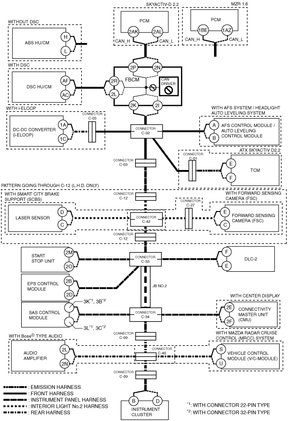
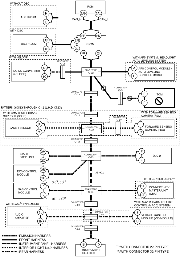
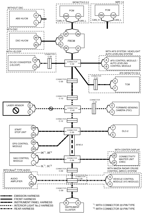
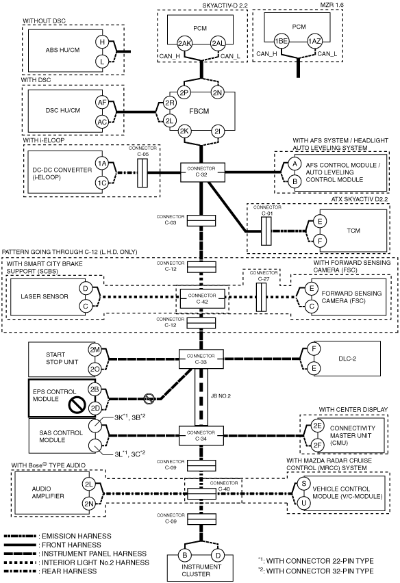
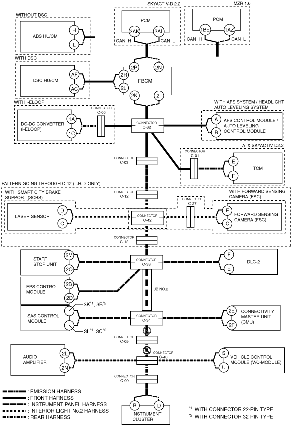
B
Possible cause
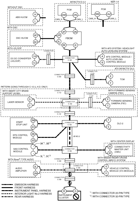
System wiring diagram
am3zzw00017862
|
Inspection item
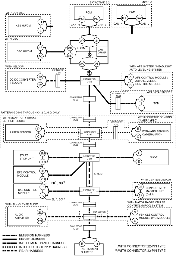
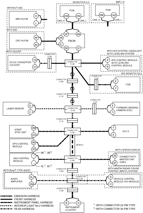
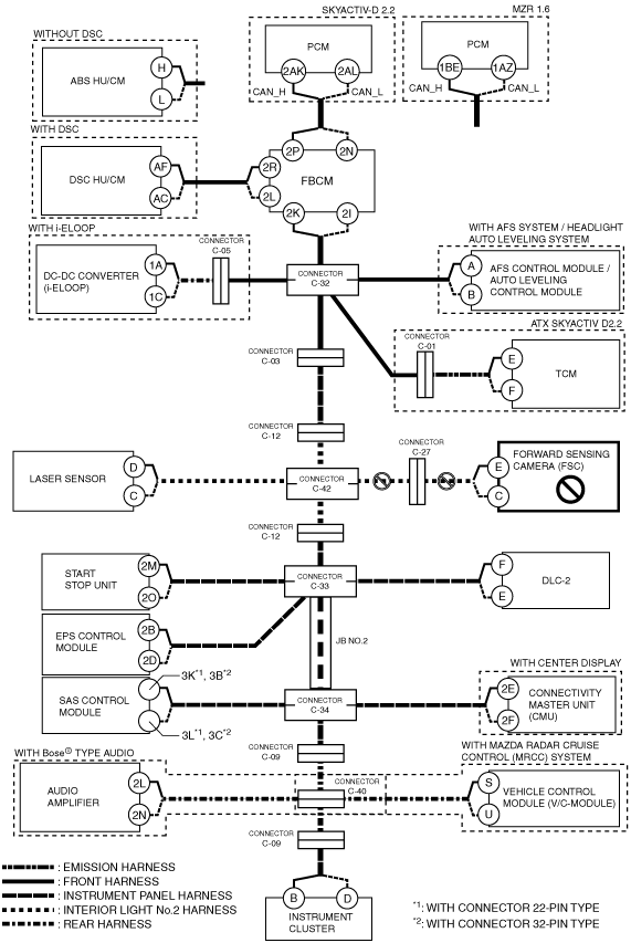
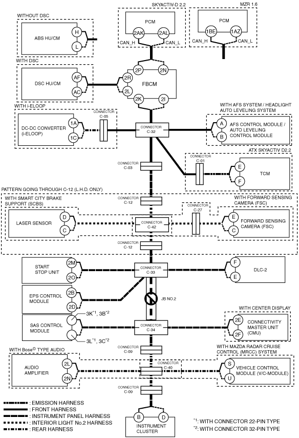
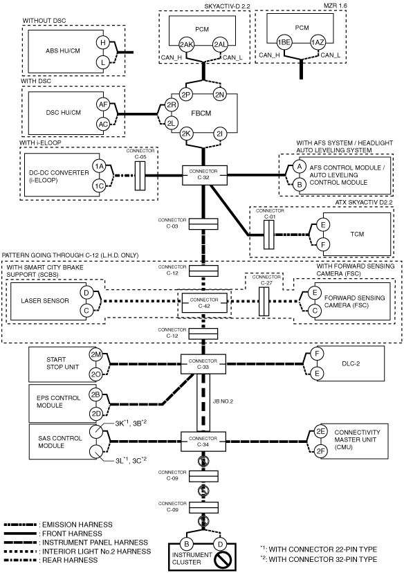
C
Possible cause
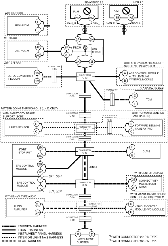
System wiring diagram
am3zzw00017863
|
Inspection item
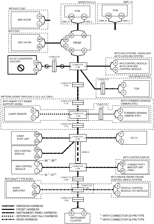
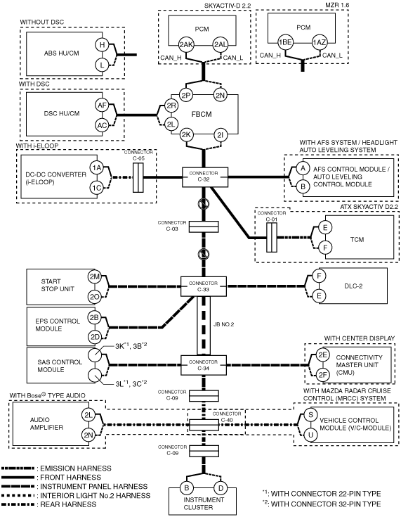
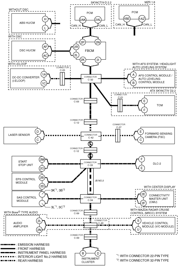
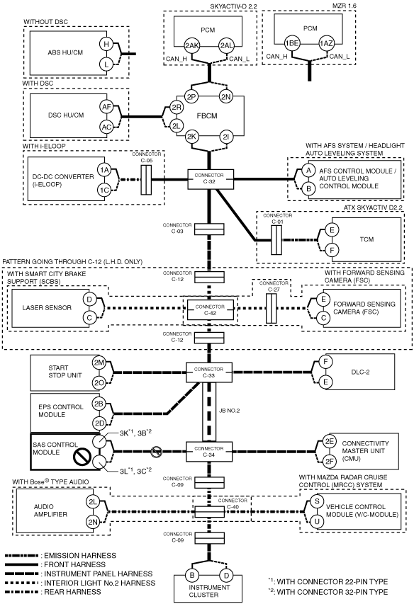
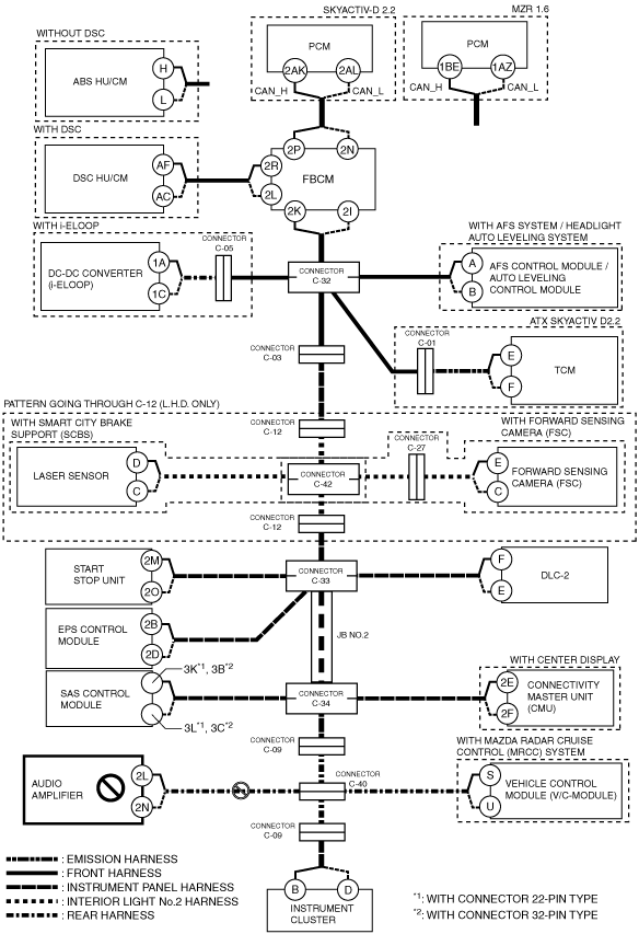
D
Possible cause
System wiring diagram
am3zzw00017864
|
Inspection item
E
Possible cause
System wiring diagram
am3zzw00017865
|
Inspection item
F
Possible cause
System wiring diagram
am3zzw00017866
|
Inspection item
G
Possible cause
System wiring diagram
am3zzw00017867
|
Inspection item
H
With smart city brake support (SCBS) and forward sensing camera (FSC)
System wiring diagram
am3zzw00017868
|
L.H.D. without smart city brake support (SCBS) or forward sensing camera (FSC)
System wiring diagram
am3zzw00017869
|
R.H.D. without smart city brake support (SCBS) or forward sensing camera (FSC)
System wiring diagram
am3zzw00017870
|
I
Possible cause
System wiring diagram
am3zzw00017871
|
Inspection item
J
Possible cause
System wiring diagram
am3zzw00017872
|
Inspection item
K
Possible cause
System wiring diagram
am3zzw00017873
|
Inspection item
L
Possible cause
System wiring diagram
am3zzw00017874
|
Inspection item
M
Possible cause
System wiring diagram
am3zzw00017875
|
Inspection item
N
Possible cause
System wiring diagram
am3zzw00017876
|
Inspection item
O
Possible cause
System wiring diagram
am3zzw00017877
|
Inspection item
P
Possible cause
System wiring diagram
am3zzw00017878
|
Inspection item
Q
With Bose® type audio and mazda radar cruise control (MRCC) system
System wiring diagram
am3zzw00017879
|
Without Bose® type audio or mazda radar cruise control (MRCC) system
System wiring diagram
am3zzw00017880
|
R
Possible cause
System wiring diagram
am3zzw00017881
|
Inspection item
S
Possible cause
System wiring diagram
am3zzw00017882
|
Inspection item
T
Possible cause
System wiring diagram
am3zzw00017883
|
Inspection item