 |
am2zzw00012618
DTC P0402:00 [SKYACTIV-D 1.5]
id0102q2155200
Details On DTCs
|
DESCRIPTION |
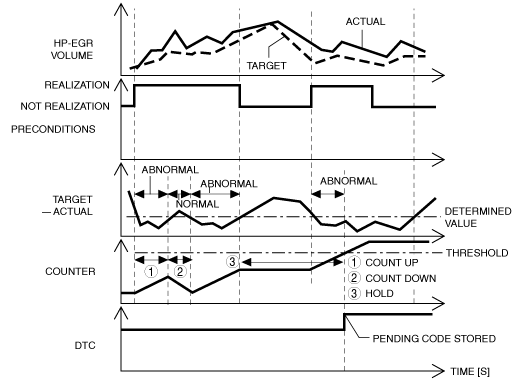
HP-EGR flow excessive detected |
|
|---|---|---|
|
DETECTION CONDITION
|
Determination conditions
|
• When the following condition is met, the HP-EGR volume is higher than the specification for the target value for a continuous specified time.
|
|
Preconditions
|
• During HP-EGR control
• Engine speed: 1,200—2,500 rpm
• Fuel injection amount:4—50 mm3/stoke
• Engine torque: 20—240 N·m {2.1—24 kgf·m, 15—177 ft·lbf}
• The following DTCs are not detected:
|
|
|
Drive cycle
|
• 1
|
|
|
Self test type
|
• CMDTC self test
|
|
|
Sensor used
|
• HP-EGR control valve
• Intake shutter valve
• LP-EGR control valve
• Exhaust shutter valve
• MAF sensor
• MAP sensor
• Boost air temperature sensor
• Exhaust gas pressure sensor No.1
• Exhaust gas temperature sensor No.1
|
|
|
FAIL-SAFE FUNCTION
|
• PCM restricts engine torque.
• Inhibits the EGR control.
• Inhibits the auto diesel particulate filter regeneration control.
• Inhibits the compulsory diesel particulate filter regeneration control.
• Inhibits engine-stop by operating the i-stop function.
|
|
|
VEHICLE STATUS WHEN DTCs ARE OUTPUT
|
• Check engine light is illuminated
|
|
|
POSSIBLE CAUSE
|
• Erratic signal to PCM
• Intake shutter valve malfunction
• HP-EGR control valve malfunction (stuck open)
• Air suction in intake air system between turbocharger with variable turbine geometry and intake manifold
• HP-EGR system passage malfunction (restriction)
• PCM malfunction
|
|
System Wiring Diagram
Function Explanation (DTC Detection Outline)
am2zzw00012618
|
Repeatability Verification Procedure
PID Item/Simulation Item Used In Diagnosis
PID/DATA monitor item table
|
Item |
Definition |
Unit |
Condition/Specification |
|---|---|---|---|
|
CACT11
|
Boost air temperature
|
°C, °F
|
• Displays the boost air temperature
|
|
EXHPRES1
|
Exhaust gas pressure (No.1)
|
kPa, Bar, psi
|
• Idle: Approx. 106 kPa {1.08 kgf/cm2, 15.4 psi}
• Racing (engine speed above 2,000 rpm): Approx. 112 kPa {1.14 kgf/cm2, 16.2 psi}
• Racing (engine speed above 4,000 rpm): Approx. 220 kPa {2.24 kgf/cm2, 31.9 psi}
|
|
EXHTEMP1
|
Exhaust gas temperature (No.1)
|
°C, °F
|
• Displays the exhaust gas temperature (No.1)
|
|
MAF
|
Mass air flow
|
g/Sec
|
• Switch ignition ON (engine off): Approx. 0.38 g/s {0.050 lb/min}
• Idle: 2.2—4.5 g/s {0.30—0.59 lb/min}
• Racing (engine speed 2,000 rpm): 8.0—9.5 g/s {1.1—1.2 lb/min}
• Racing (engine speed 4,000 rpm): 50—56 g/s {6.7—7.4 lb/min}
|
|
MAP
|
Manifold absolute pressure input from MAP sensor
|
kPa, Bar, psi
|
• Switch ignition ON (engine off): Approx. 100.37 kPa {1.0235 kgf/cm2, 14.557 psi}
• Idle: Approx. 82 kPa {0.84 kgf/cm2, 12 psi}
|
Function Inspection Using M-MDS
|
STEP |
INSPECTION |
ACTION |
|
|---|---|---|---|
|
1
|
PURPOSE: RECORD VEHICLE STATUS AT TIME OF DTC DETECTION TO UTILIZE WITH REPEATABILITY VERIFICATION
• Record the FREEZE FRAME DATA/snapshot data on the repair order.
|
—
|
Go to the next step.
|
|
2
|
PURPOSE: VERIFY RELATED SERVICE INFORMATION AVAILABILITY
• Verify related Service Information availability.
• Is any related Service Information available?
|
Yes
|
Perform repair or diagnosis according to the available Service Information.
• If the vehicle is not repaired, go to the next step.
|
|
No
|
Go to the next step.
|
||
|
3
|
PURPOSE: IDENTIFY TRIGGER DTC FOR FREEZE FRAME DATA
• Is the DTC P0402:00 on FREEZE FRAME DATA?
|
Yes
|
Go to the next step.
|
|
No
|
Go to the troubleshooting procedure for DTC on FREEZE FRAME DATA.
(See DTC TABLE [SKYACTIV-D 1.5].)
|
||
|
4
|
PURPOSE: VERIFY IF DIAGNOSTIC RESULT IS AFFECTED BY OTHER RELATED DTCs OCCURRING
• Switch the ignition off, then ON (engine off).
• Perform the Pending Trouble Code Access Procedure and DTC Reading Procedure.
• Is the other PENDING CODE/DTC also present?
|
Yes
|
Go to the applicable DTC inspection.
(See DTC TABLE [SKYACTIV-D 1.5].)
|
|
No
|
Go to the next step.
|
||
|
5
|
PURPOSE: VERIFY IF THERE IS PID ITEM CAUSING DRASTIC CHANGES OF ACCELERATION FLUCTUATION BY INPUT SIGNAL TO PCM
• Access the following PIDs using the M-MDS:
PCM:
• Is there any signal that is far out of specification?
|
Yes
|
Go to the next step.
|
|
No
|
Go to the troubleshooting procedure to perform the procedure from Step 1.
|
||
|
6
|
PURPOSE: VERIFY CONNECTOR CONNECTIONS
• Access the following PIDs using the M-MDS:
PCM:
• When the following parts are shaken, does the PID value include a PID item which has changed?
|
Yes
|
Repair or replace the applicable connector parts.
Go to the troubleshooting procedure to perform the procedure from Step 5.
|
|
No
|
Go to the troubleshooting procedure to perform the procedure from Step 1.
|
||
Troubleshooting Diagnostic Procedure
|
STEP |
INSPECTION |
ACTION |
|
|---|---|---|---|
|
1
|
PURPOSE: INSPECT INTAKE SHUTTER VALVE CONTROL SYSTEM OPERATION
• Perform the Intake Shutter Valve Operation Inspection.
• Is there any malfunction?
|
Yes
|
Repair or replace the malfunctioning part according to the inspection results, then go to Step 5.
|
|
No
|
Go to the next step.
|
||
|
2
|
PURPOSE: INSPECT HP-EGR CONTROL VALVE CONTROL SYSTEM OPERATION
• Perform the HP-EGR Control Valve Operation Inspection.
• Is there any malfunction?
|
Yes
|
Repair or replace the malfunctioning part according to the inspection results, then go to Step 5.
|
|
No
|
Go to the next step.
|
||
|
3
|
PURPOSE: INSPECT INTAKE AIR SYSTEM FOR AIR SUCTION
• Inspect for air leakage at the following:
• Is there any malfunction?
|
Yes
|
Repair or replace the malfunctioning part according to the inspection results, then go to Step 5.
|
|
No
|
Go to the next step.
|
||
|
4
|
PURPOSE: INSPECT FOR RESTRICTION OR CLOGGED IN HP-EGR PASSAGE
• Switch the ignition off.
• Remove the HP-EGR control valve.
• Visually inspect the HP-EGR passage for clogging and the gasket correctly installed.
• Is there any malfunction?
|
Yes
|
Repair or replace the malfunctioning part according to the inspection results, then go to the next step.
|
|
No
|
Go to the next step.
|
||
|
5
|
PURPOSE: PERFORM DTC INSPECTION AND VERIFY IF MALFUNCTIONING PART IS PCM
• Always reconnect all disconnected connectors.
• Clear the DTC from the PCM memory using the M-MDS.
• Implement the repeatability verification procedure.
• Perform the DTC Reading Procedure.
• Is the same DTC present?
|
Yes
|
Repeat the inspection from Step 1.
• If the malfunction recurs, replace the PCM.
Go to the next step.
|
|
No
|
Go to the next step.
|
||
|
6
|
PURPOSE: VERIFY AFTER REPAIR PROCEDURE
• Perform the “AFTER REPAIR PROCEDURE”.
• Are any DTCs present?
|
Yes
|
Go to the applicable DTC inspection.
(See DTC TABLE [SKYACTIV-D 1.5].)
|
|
No
|
DTC troubleshooting completed.
|
||