|
1
|
RECORD VEHICLE STATUS AT TIME OF DTC DETECTION TO UTILIZE WITH REPEATABILITY VERIFICATION
-
Note
-
• Recording can be facilitated using the screen capture function of the PC.
• Record the FREEZE FRAME DATA/snapshot data on the repair order.
|
—
|
Go to the next step.
|
|
2
|
VERIFY RELATED SERVICE INFORMATION AVAILABILITY
• Verify related Service Information availability.
• Is any related Service Information available?
|
Yes
|
Perform repair or diagnosis according to the available Service Information.
• If the vehicle is not repaired, go to the next step.
|
|
No
|
Go to the next step.
|
|
3
|
INSPECT SPEED SENSOR ASSY (TURBOCHARGER WITH VARIABLE TURBINE GEOMETRY) CONNECTOR CONDITION
• Switch the ignition off.
• Disconnect the speed sensor assy (turbocharger with variable turbine geometry) connector.
• Inspect for poor connection (such as damaged/pulled-out pins, corrosion).
• Is there any malfunction?
|
Yes
|
Repair or replace the connector and/or terminals, then go to Step 9.
|
|
No
|
Go to the next step.
|
|
4
|
INSPECT PCM CONNECTOR CONDITION
• Disconnect the PCM connector.
• Inspect for poor connection (such as damaged/pulled-out pins, corrosion).
• Is there any malfunction?
|
Yes
|
Repair or replace the connector and/or terminals, then go to Step 9.
|
|
No
|
Go to the next step.
|
|
5
|
INSPECT SPEED SENSOR ASSY (TURBOCHARGER WITH VARIABLE TURBINE GEOMETRY) CIRCUIT FOR SHORT TO POWER SUPPLY
• Verify that the speed sensor assy (turbocharger with variable turbine geometry) and PCM connectors are disconnected.
• Switch the ignition ON (engine off).
-
Note
-
• Another DTC may be stored by the PCM detecting an open circuit.
• Measure the voltage at the following terminals (wiring harness-side):
-
― Speed sensor assy (turbocharger with variable turbine geometry) terminal A
― Speed sensor assy (turbocharger with variable turbine geometry) terminal B
• Is the voltage 0 V?
|
Yes
|
Go to the next step.
|
|
No
|
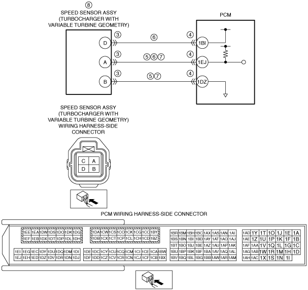
Refer to the wiring diagram and verify whether or not there is a common connector between the following terminals:
• Speed sensor assy (turbocharger with variable turbine geometry) terminal A—PCM terminal 1EJ
• Speed sensor assy (turbocharger with variable turbine geometry) terminal B—PCM terminal 1DZ
If there is a common connector:
• Determine the malfunctioning part by inspecting the common connector and the terminal for corrosion, damage, or pin disconnection, and the common wiring harness for a short to power supply.
• Repair or replace the malfunctioning part.
If there is no common connector:
• Repair or replace the wiring harness which has a short to power supply.
Go to Step 9.
|
|
6
|
INSPECT SPEED SENSOR ASSY (TURBOCHARGER WITH VARIABLE TURBINE GEOMETRY) POWER SUPPLY CIRCUIT AND SIGNAL CIRCUIT FOR SHORT TO EACH OTHER
• Verify that the speed sensor assy (turbocharger with variable turbine geometry) and PCM connectors are disconnected.
• Switch the ignition off.
• Inspect for continuity between speed sensor assy (turbocharger with variable turbine geometry) terminals D and A (wiring harness-side).
• Is there continuity?
|
Yes
|
Refer to the wiring diagram and verify whether or not there is a common connector between the following terminals:
• Speed sensor assy (turbocharger with variable turbine geometry) terminal D—PCM terminal 1BI
• Speed sensor assy (turbocharger with variable turbine geometry) terminal A—PCM terminal 1EJ
If there is a common connector:
• Determine the malfunctioning part by inspecting the common connector and the terminal for corrosion, damage, or pin disconnection, and the common wiring harness for a short to each other.
• Repair or replace the malfunctioning part.
If there is no common connector:
• Repair or replace the wiring harness which has a short to each other.
Go to Step 9.
|
|
No
|
Go to the next step.
|
|
7
|
INSPECT SPEED SENSOR ASSY (TURBOCHARGER WITH VARIABLE TURBINE GEOMETRY) CIRCUIT FOR OPEN CIRCUIT
• Verify that the speed sensor assy (turbocharger with variable turbine geometry) and PCM connectors are disconnected.
• Inspect for continuity between the following terminals (wiring harness-side):
-
― Speed sensor assy (turbocharger with variable turbine geometry) terminal A—PCM terminal 1EJ
― Speed sensor assy (turbocharger with variable turbine geometry) terminal B—PCM terminal 1DZ
• Is there continuity?
|
Yes
|
Go to the next step.
|
|
No
|
Refer to the wiring diagram and verify whether or not there is a common connector between the following terminals:
• Speed sensor assy (turbocharger with variable turbine geometry) terminal A—PCM terminal 1EJ
• Speed sensor assy (turbocharger with variable turbine geometry) terminal B—PCM terminal 1DZ
If there is a common connector:
• Determine the malfunctioning part by inspecting the common connector and the terminal for corrosion, damage, or pin disconnection, and the common wiring harness for an open circuit.
• Repair or replace the malfunctioning part.
If there is no common connector:
• Repair or replace the wiring harness which has an open circuit.
Go to Step 9.
|
|
8
|
INSPECT SPEED SENSOR ASSY (TURBOCHARGER WITH VARIABLE TURBINE GEOMETRY)
• Reconnect all disconnected connectors.
• Inspect the speed sensor assy (turbocharger with variable turbine geometry).
• Is there any malfunction?
|
Yes
|
Replace the speed sensor assy (turbocharger with variable turbine geometry), then go to the next step.
|
|
No
|
Go to the next step.
|
|
9
|
VERIFY DTC TROUBLESHOOTING COMPLETED
• Always reconnect all disconnected connectors.
• Clear the DTC from the PCM memory using the M-MDS.
• Perform the following:
-
1. Access the EOT PID using the M-MDS.
2. Wait until the EOT PID value is below 50 °C {122 °F}.
3. Start the engine without depressing the accelerator pedal, and let the engine idle for 30 s.
4. Repeat Steps 1 to 3 operations above in succession.
• Perform the DTC Reading Procedure.
• Is the DTC P2581:00 or P2580:00 also present?
|
Yes
|
Repeat the inspection from Step 1.
• If the malfunction recurs, replace the turbocharger with variable turbine geometry, and then perform Step 8 again.
• If the malfunction recurs, replace the PCM.
Go to the next step.
|
|
No
|
Go to the next step.
|
|
10
|
VERIFY AFTER REPAIR PROCEDURE
• Perform the “AFTER REPAIR PROCEDURE”.
• Are any DTCs present?
|
Yes
|
Go to the applicable DTC inspection.
|
|
No
|
DTC troubleshooting completed.
|