 |
am3zzw00017388
TURBOCHARGER WITH VARIABLE TURBINE GEOMETRY REMOVAL/INSTALLATION [SKYACTIV-D 1.5]
id0113q2707500
Operation After Replacing or Removal/Installation Turbocharger
1. If the turbocharger is replaced or removed/installed, perform the following procedure.
|
STEP |
ACTION |
PAGE/CONDITION |
|---|---|---|
|
1
|
Perform turbocharger initialization procedure.
|
|
|
2
|
Switch the ignition off.
|
—
|
|
3
|
Wait for 20 s.
|
—
|
|
4
|
Start the engine.
|
—
|
|
5
|
Maintain the engine idling condition for 10 s.
|
—
|
|
6
|
Switch the ignition off.
|
—
|
|
7
|
Wait for 20 s.
|
—
|
|
8
|
Perform KOEO self-test procedure.
|
|
|
9
|
Perform KOER self-test procedure.
|
Turbocharger With Variable Turbine Geometry Removal/Installation
1. Disconnect the negative battery cable. (See NEGATIVE BATTERY CABLE DISCONNECTION/CONNECTION [SKYACTIV-D 1.5].)
2. Remove the engine cover. (See ENGINE COVER REMOVAL/INSTALLATION [SKYACTIV-D 1.5].)
3. Drain the engine coolant. (See ENGINE COOLANT REPLACEMENT [SKYACTIV-D 1.5].)
4. Remove the following parts: (See INTAKE-AIR SYSTEM REMOVAL/INSTALLATION [SKYACTIV-D 1.5].)
5. Remove the battery and the battery tray. (See BATTERY REMOVAL/INSTALLATION [SKYACTIV-D 1.5].)
6. Remove the following parts as a single unit: (See INTAKE-AIR SYSTEM REMOVAL/INSTALLATION [SKYACTIV-D 1.5].)
7. Remove the turbocharger air outlet pipe. (See INTAKE-AIR SYSTEM REMOVAL/INSTALLATION [SKYACTIV-D 1.5].)
8. Remove the front crossmember. (See FRONT CROSSMEMBER REMOVAL/INSTALLATION [SKYACTIV-D 1.5, SKYACTIV-D 2.2].)
9. Remove the catalytic converter (DPF). (See EXHAUST SYSTEM REMOVAL/INSTALLATION [SKYACTIV-D 1.5].)
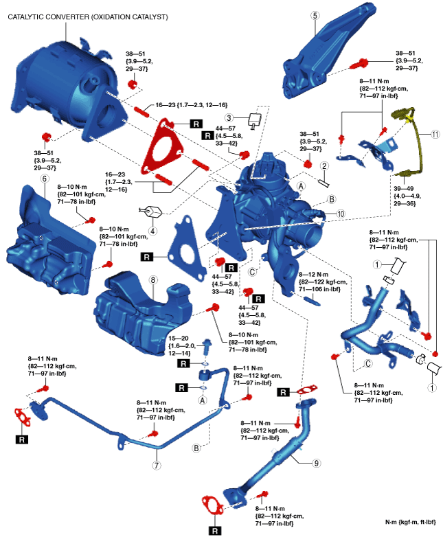
10. Remove in the order shown in the figure.
11. Install in the reverse order of removal.
12. Refill the engine coolant. (See ENGINE COOLANT REPLACEMENT [SKYACTIV-D 1.5].)
13. Perform the following procedure.
am3zzw00017388
|
|
1
|
Heater hose
|
|
2
|
Vacuum hose
|
|
3
|
Turbocharger actuator connector
|
|
4
|
Speed sensor assy connector
|
|
5
|
Turbocharger bracket
|
|
6
|
Insulator
|
|
7
|
Oil main pipe
(See Oil main pipe removal note.)
|
|
8
|
Insulator
|
|
9
|
Oil return pipe
|
|
10
|
Turbocharger with variable turbine geometry
|
|
11
|
Exhaust gas temperature sensor No.1
|
Oil main pipe removal note
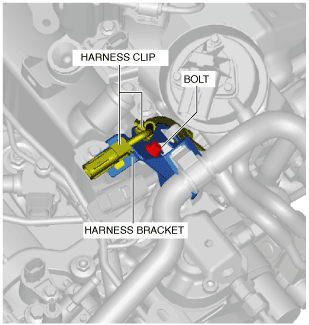
1. Disconnect the exhaust gas temperature sensor No.1. (See EXHAUST GAS TEMPERATURE SENSOR REMOVAL/INSTALLATION [SKYACTIV-D 1.5].)
2. Remove the wiring harness bracket shown in the figure.
am2zzw00012041
|
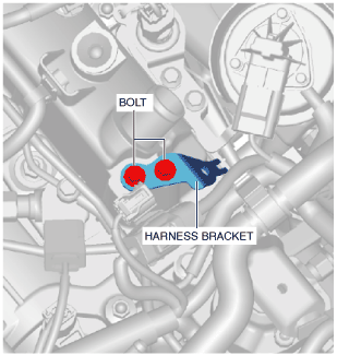
3. Disconnect the exhaust gas pressure sensor No.1. (See EXHAUST GAS PRESSURE SENSOR REMOVAL/INSTALLATION [SKYACTIV-D 1.5].)
4. Remove the wiring harness bracket shown in the figure.
am2zzw00012042
|
5. Remove the oil main pipe.
Oil main pipe installation note
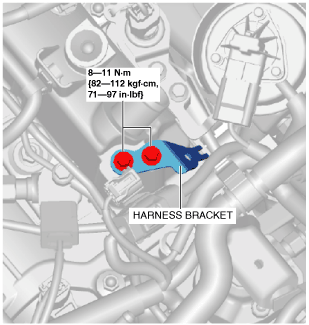
1. Install the oil main pipe.
2. Install the harness bracket as shown in the figure.
ac3wzw00001373
|
3. Connect the exhaust gas pressure sensor No.1 connector. (See EXHAUST GAS PRESSURE SENSOR REMOVAL/INSTALLATION [SKYACTIV-D 1.5].)
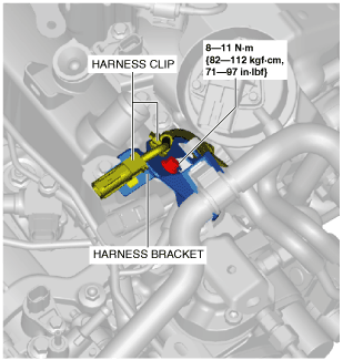
4. Install the harness bracket as shown in the figure.
ac3wzw00001374
|
5. Connect the exhaust gas temperature sensor No.1 connector. (See EXHAUST GAS TEMPERATURE SENSOR REMOVAL/INSTALLATION [SKYACTIV-D 1.5].)
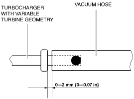
Vacuum hose installation note
1. Install the vacuum hose as shown in the figure.
ac3wzw00001375
|