 |
am3zzw00015789
FRONT CROSSMEMBER REMOVAL/INSTALLATION [SKYACTIV-D 1.5, SKYACTIV-D 2.2]
id0213008010f3
1. Remove the joint cover. (See STEERING WHEEL AND COLUMN REMOVAL/INSTALLATION.)
2. Disconnect the intermediate shaft from the steering gear and linkage. (See STEERING WHEEL AND COLUMN REMOVAL/INSTALLATION.)
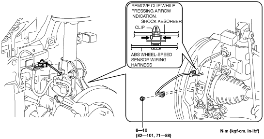
3. Disconnect the front ABS wheel-speed sensor wiring harness installed to the steering knuckle and set it aside. (See FRONT ABS WHEEL-SPEED SENSOR REMOVAL/INSTALLATION.)
am3zzw00015789
|
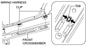
4. Remove the front under cover No.2. (See FRONT UNDER COVER No.2 REMOVAL/INSTALLATION.)
5. Disconnect the wiring harness from the front crossmember. (Vehicle with i-ELOOP)
am6zzw00008428
|
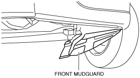
6. Remove the front under cover No.1. (See FRONT UNDER COVER No.1 REMOVAL/INSTALLATION.)
7. Remove the splash shield. (See SPLASH SHIELD REMOVAL/INSTALLATION.)
8. Set the front mudguard away from the front crossmember and front bumper. (See MUDGUARD REMOVAL/INSTALLATION.)
am6zzw00008429
|
9. Disconnect the front crossmember extension.
ac5uuw00000131
|
10. Disconnect the front stabilizer control link (front stabilizer side). (See FRONT STABILIZER REMOVAL/INSTALLATION.)
ac5uuw00000128
|
11. Remove the insulator. (See EXHAUST SYSTEM REMOVAL/INSTALLATION [SKYACTIV-D 1.5].) (See EXHAUST SYSTEM REMOVAL/INSTALLATION [SKYACTIV-D 2.2].)
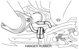
12. Disconnect the hanger rubber from the front crossmember and set it aside.
am6zzw00008953
|
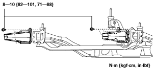
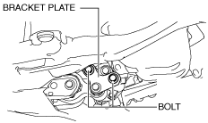
13. Loosen the bolts shown in the figure.
SKYACTIV-D 1.5
am3zzw00017930
|
SKYACTIV-D 2.2
am3zzw00014669
|
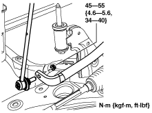
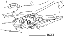
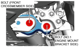
14. Remove the bolt shown in the figure.
SKYACTIV-D 1.5
am3zzw00017931
|
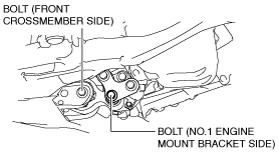
SKYACTIV-D 2.2
am3zzw00014737
|
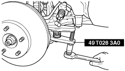
15. Remove the tie-rod end locknut.
16. Detach the tie-rod end from the steering knuckle using the SST.
ac5uuw00000134
|
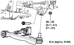
17. Disconnect the front lower arm ball joint.
ac5uuw00000135
|
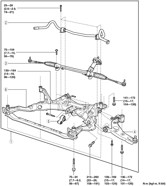
18. Remove in the order indicated in the table.
19. Install in the reverse order of removal.
20. Inspect the wheel alignment and adjust it if necessary. (See FRONT WHEEL ALIGNMENT.)
am3zzw00016891
|
|
1
|
Front crossmember component
|
|
2
|
Front stabilizer
|
|
3
|
Steering gear and linkage
|
|
4
|
Front lower arm
|
|
5
|
No.1 engine mount rubber
|
|
6
|
Front crossmember
|
Front Crossmember Component Removal Note
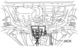
1. Support the front crossmember component using a jack.
ac5uuw00000137
|
2. Remove the front crossmember installation bolts.
3. Remove the front crossmember, front stabilizer, front lower arm, and steering gear and linkage as a single unit.
No.1 Engine Mount Rubber and Front Crossmember Component Installation Note
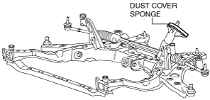
1. When installing the front crossmember component to the vehicle, assemble the dust cover to the body-side installation area correctly to prevent water or foreign matter from penetrating. Install the dust cover carefully so as not to pinch the dust cover sponge to the body-side installation area or put a fold line on the sponge by contact.
am6zzw00010934
|
2. Temporarily tighten the bolts shown in the figure.
SKYACTIV-D 1.5
am3zzw00017932
|
SKYACTIV-D 2.2
am3zzw00014738
|
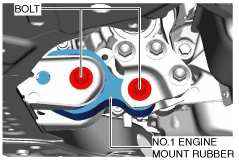
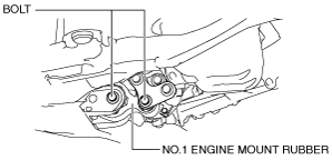
3. Install the No.1 engine mount rubber and temporarily tighten the bolts shown in the figure.
SKYACTIV-D 1.5
am3zzw00017933
|
SKYACTIV-D 2.2
am3zzw00014739
|
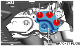
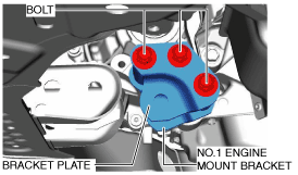
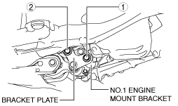
4. Tighten the No.1 engine mount bracket and bracket plate installation bolts in the order shown in the figure.
SKYACTIV-D 1.5
am3zzw00017934
|
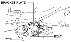
SKYACTIV-D 2.2
am3zzw00014677
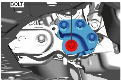
|
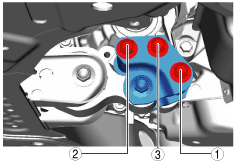
5. Tighten the No.1 engine mount rubber installation bolts shown in the figure.
SKYACTIV-D 1.5
am3zzw00017935
|
SKYACTIV-D 2.2
am3zzw00014740
|
Tightening torque
|
Installation position |
Tightening torque |
|---|---|
|
No.1 engine mount bracket side
|
130—151 N·m {14—15 kgf·m, 96—111 ft·lbf}
|
|
Front crossmember side
|
130—164 N·m {14—16 kgf·m, 96—120 ft·lbf}
|