 |
am3zzw00017459
EXHAUST SYSTEM REMOVAL/INSTALLATION [SKYACTIV-D 1.5]
id0115q2800200
Catalytic Converter (DPF) Replacement Procedure
1. If the catalytic converter (DPF) is replaced, perform the following procedure.
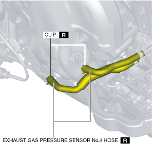
|
STEP |
ACTION |
PAGE/CONDITION |
|---|---|---|
|
1
|
Perform DPF data reset procedure.
|
|
|
2
|
Switch the ignition off.
|
—
|
|
3
|
Wait for 20 s or more.
|
—
|
|
4
|
Perform KOEO self-test procedure.
|
|
|
5
|
Perform KOER self-test procedure.
|
|
|
6
|
Perform fuel injector injection amount correction.
|
|
|
7
|
Perform compulsory diesel particulate filter regeneration.
|
|
|
8
|
Clear the DTCs.
|
Exhaust Shutter Valve Replacement Procedure
1. If the exhaust shutter valve is replaced, perform the following procedure.
|
STEP |
ACTION |
PAGE/CONDITION |
|---|---|---|
|
1
|
Perform exhaust shutter valve initialization procedure.
|
|
|
2
|
Warm the engine until the engine coolant temperature is 70 °C.
|
—
|
|
3
|
Switch the ignition off.
|
—
|
|
4
|
Wait for 20 s or more.
|
—
|
|
5
|
Start the engine.
|
—
|
|
6
|
Maintain the engine idling condition for 10 s.
|
—
|
|
7
|
Switch the ignition off.
|
—
|
|
8
|
Wait for 20 s or more.
|
—
|
|
9
|
Perform KOEO self-test procedure.
|
|
|
10
|
Perform KOER self-test procedure.
|
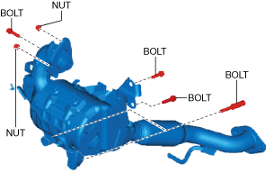
Exhaust System Removal /Installation
1. Disconnect the negative battery cable. (See NEGATIVE BATTERY CABLE DISCONNECTION/CONNECTION [SKYACTIV-D 1.5].)
2. Remove the front under cover No.2. (See FRONT UNDER COVER No.2 REMOVAL/INSTALLATION.)
3. Drain the engine coolant. (See ENGINE COOLANT REPLACEMENT [SKYACTIV-D 1.5].)
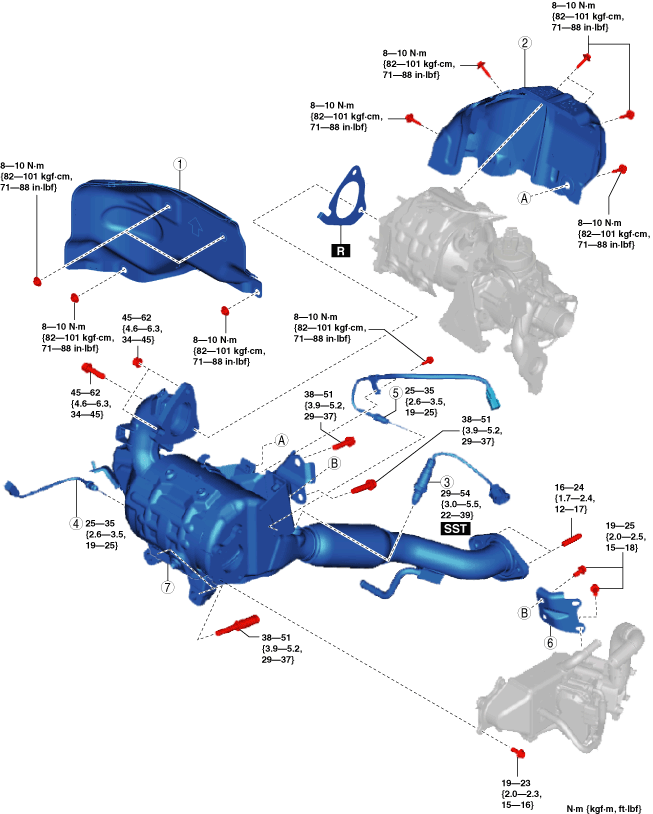
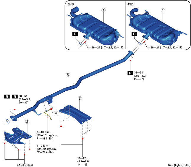
4. Remove in the order shown in the figure.
5. Remove the exhaust system insulator. (See Exhaust system insulator removal/installation.)
6. Install in the reverse order of removal.
Step 1
am3zzw00017459
|
|
1
|
Main silencer
|
|
2
|
Tunnel member
|
|
3
|
Plate
|
|
4
|
Exhaust shutter valve
|
|
5
|
Middle pipe
|
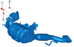
Step 2
am3zzw00017460
|
|
1
|
Insulator
|
|
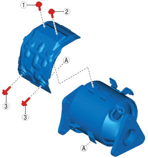
2
|
Catalytic converter (DPF) insulator
|
|
3
|
A/F sensor
|
|
4
|
Exhaust gas temperature sensor No.3
|
|
5
|
Exhaust gas temperature sensor No.4
|
|
6
|
Bracket
|
|
7
|
Catalytic converter (DPF)
|
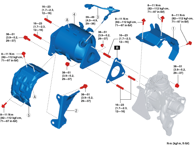
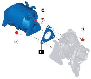
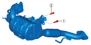
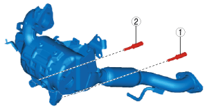
Step 3
am3zzw00017461
|
|
1
|
Turbocharger insulator
|
|
2
|
Catalytic converter (oxidation catalyst) bracket
|
|
3
|
Exhaust gas temperature sensor No.2
|
|
4
|
Catalytic converter (oxidation catalyst)
|
|
5
|
Catalytic converter (oxidation catalyst) insulator
|
Exhaust system insulator removal/installation
1. Remove the floor under cover. (See FLOOR UNDER COVER REMOVAL/INSTALLATION.)
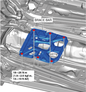
2. Remove the brace bar.
am3zzw00017462
|
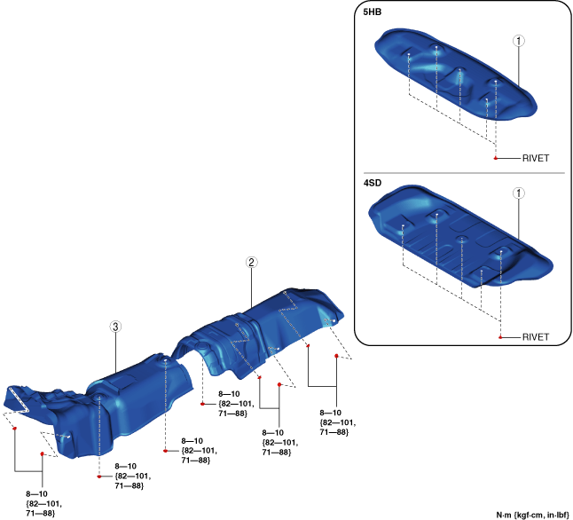
3. Remove in the order shown in the figure.
4. Install in the reverse order of removal.
am3zzw00017463
|
|
1
|
Insulator (rear)
|
|
2
|
Insulator (middle)
|
|
3
|
Insulator (front)
|
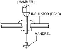
Insulator (rear) removal note
1. Using a hammer and punch (diam. 2—2.8 mm{0.08—0.11 in}), punch out the mandrel.
am6zzw00011733
|
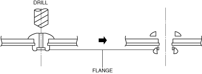
2. Pull out and remove the flange using a drill (diam. 5 mm {0.2 in}).
am6zzw00011734
|
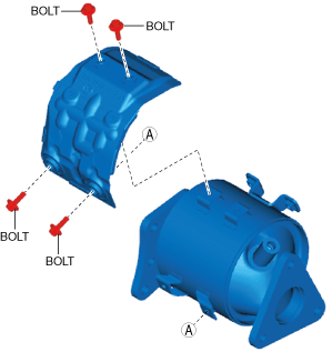
Catalytic converter (DPF) Insulator removal note [R.H.D.]
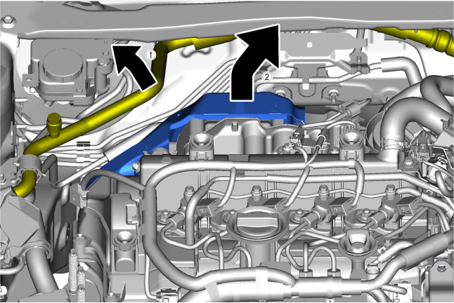
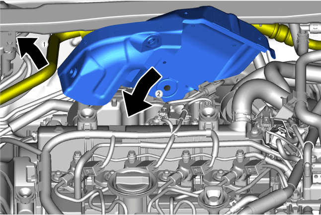
1. While setting the cooler hose (LO) aside, remove the catalytic converter (DPF) insulator in the direction of the arrow.
am3zzw00017464
|
Catalytic converter (DPF) removal note
1. Remove the front crossmember. (See FRONT CROSSMEMBER REMOVAL/INSTALLATION [SKYACTIV-D 1.5, SKYACTIV-D 2.2].)
2. Remove the battery and the battery tray. (See BATTERY REMOVAL/INSTALLATION [SKYACTIV-D 1.5].)
3. Disconnect the LP-EGR pipe from the turbocharger air inlet hose. (See LP-EGR CONTROL VALVE REMOVAL/INSTALLATION [SKYACTIV-D 1.5].)
4. Remove the drive shaft bracket. (See FRONT DRIVE SHAFT REMOVAL/INSTALLATION.)
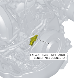
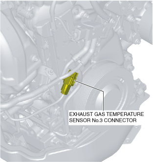
5. Disconnect exhaust gas temperature sensor No.3 connector shown in the figure.(See EXHAUST GAS TEMPERATURE SENSOR REMOVAL/INSTALLATION [SKYACTIV-D 1.5].)
am2zzw00012150
|
6. Disconnect the exhaust gas pressure sensor No.2 hose on the catalytic converter (DPF) side shown in the figure.(See EXHAUST GAS PRESSURE SENSOR REMOVAL/INSTALLATION [SKYACTIV-D 1.5].)
am3zzw00037596
|
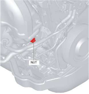
7. Remove the nut shown in the figure and set the bracket aside.
ac3wzw00001713
|
8. Disconnect the connectors of the following parts:
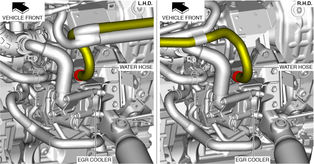
9. Disconnect the water hose shown in the figure.
am3zzw00017465
|
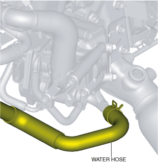
10. Disconnect the water hose shown in the figure.
ac3wzw00001714
|
11. Remove the bolts shown in the figure and set the wiring harness bracket aside.
am2zzw00012154
|
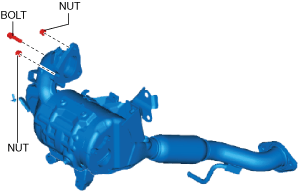
12. Remove the catalytic converter (DPF) installation nuts and bolt.
ac3wzw00001715
|
ac3wzw00001716
|
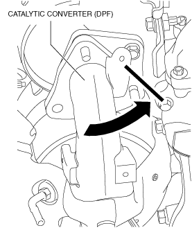
13. Move the catalytic converter (DPF) to the position shown in the figure.
ac3wzw00001717
|
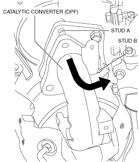
14. Pivoting on stud A, move the catalytic converter (DPF) in the direction of the arrow shown in the figure until stud B is removed.
ac3wzw00001718
|
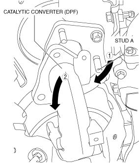
15. Move the catalytic converter (DPF) in the direction of arrow 1 along the notch groove adjoining stud A, and remove the catalytic converter (DPF) in the direction of arrow 2 as shown in the figure.
ac3wzw00001719
|
Catalytic converter (oxidation catalyst) bracket removal note
1. Remove the nuts and bolts of the catalytic converter (oxidation catalyst).
2. Remove the catalytic converter (oxidation catalyst) bracket.
Catalytic converter (oxidation catalyst) insulator installation note
1. Temporarily tighten the bolts shown in the figure until they contact the opposing part.
am2zzw00012156
|
2. Tighten the bolts in the order shown in the figure.
am2zzw00012157
|
Catalytic converter (oxidation catalyst) installation note
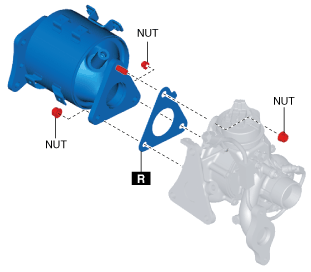
1. Temporarily tighten the nuts shown in the figure until they contact the opposing part.
am2zzw00012158
|
2. Tighten the nuts in the order shown in the figure.
am2zzw00012159
|
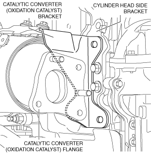
Catalytic converter (oxidation catalyst) bracket installation note
1. Align the catalytic converter (oxidation catalyst) bracket along the flange and cylinder head side bracket of the catalytic converter (oxidation catalyst) position.
am2zzw00012160
|
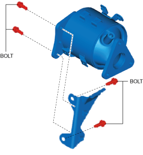
2. Temporarily tighten the bolts shown in the figure until they contact the opposing part.
am2zzw00012161
|
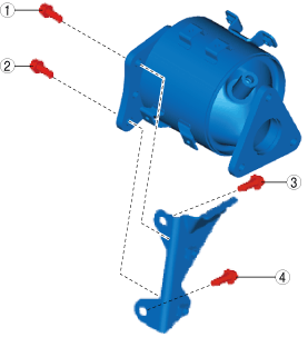
3. Tighten the bolts in the order shown in the figure.
am2zzw00012162
|
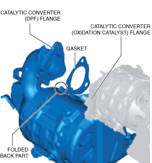
Catalytic converter (DPF) installation note
am2zzw00012163
|
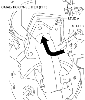
1. Move the catalytic converter (DPF) in the direction of arrow 2 along the notch groove adjoining stud A, and install the catalytic converter (DPF) in the direction of arrow 1 as shown in the figure.
ac3wzw00001720
|
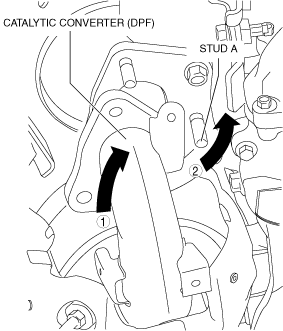
2. Install the catalytic converter (DPF) to stud B by pivoting it in the direction of the arrow on stud A.
ac3wzw00001721
|
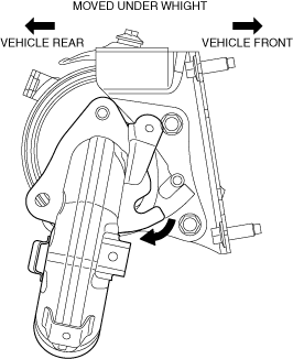
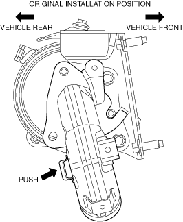
3. Move the catalytic converter from the position where it rests under its own weight to its original installation position.
ac3wzw00001722
|
4. Temporarily tighten the bolts and nuts shown in the figure until they contact the opposing part.
am3zzw00017959
|
5. Tighten the bolts and nuts in the order shown in the figure.
am2zzw00012165
|
6. Tighten the bolts in the order shown in the figure.
am3zzw00017960
|
7. Tighten the bolts in the order shown in the figure.
am2zzw00012167
|
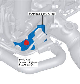
8. Install the harness bracket shown in the figure.
ac3wzw00001723
|
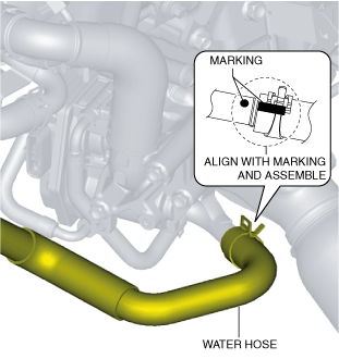
9. Install the water hose shown in the figure.
ac3wzw00001724
|
10. Install the water hose shown in the figure.
am3zzw00017465
|
11. Connect the connectors of the following parts:
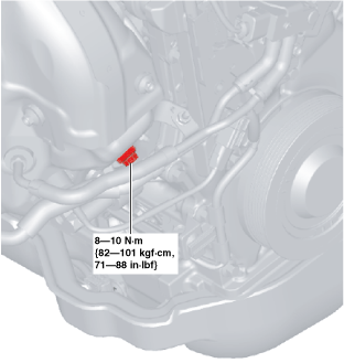
12. Install the nut shown in the figure.
ac3wzw00001726
|
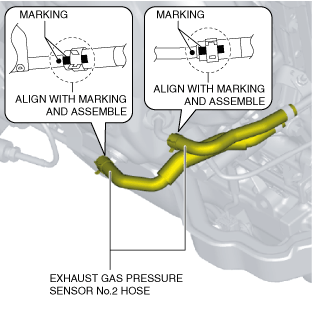
13. Connect the hose of the exhaust gas pressure sensor No.2 shown in the figure.
ac3wzw00001727
|
14. Connect the hose of the exhaust gas temperature sensor No.3 connector shown in the figure.
ac3wzw00001728
|
15. Install the drive shaft bracket. (See FRONT DRIVE SHAFT REMOVAL/INSTALLATION.)
16. Install the LP-EGR pipe. (See LP-EGR CONTROL VALVE REMOVAL/INSTALLATION [SKYACTIV-D 1.5].)
17. Install the battery and the battery tray. (See BATTERY REMOVAL/INSTALLATION [SKYACTIV-D 1.5].)
18. Install the front crossmember. (See FRONT CROSSMEMBER REMOVAL/INSTALLATION [SKYACTIV-D 1.5, SKYACTIV-D 2.2].)
Catalytic converter (DPF) insulator installation note [R.H.D.]
1. While setting the cooler hose (LO) aside, install the catalytic converter (DPF) insulator in the direction of the arrow.
am3zzw00017466
|
2. Temporarily tighten the bolts shown in the figure until they contact the opposing part.
am2zzw00012168
|
3. Tighten the bolts in the order shown in the figure.
am2zzw00012169
|