 |
am3zzw00017185
ENGINE MOUNT DISASSEMBLY/ASSEMBLY [SKYACTIV-D 1.5]
id0110q2806900
No.1 Engine Mount
1. Remove the front under cover No.2. (See FRONT UNDER COVER No.2 REMOVAL/INSTALLATION.)
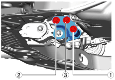
2. Remove in the order indicated in the table.
3. Install in the reverse order of removal.
am3zzw00017185
|
|
1
|
No.1 Engine Mount Rubber
|
|
2
|
Bracket Plate
|
|
3
|
No.1 Engine Mount Bracket
|
No.1 Engine Mount Rubber Removal Note
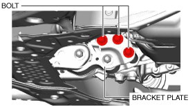
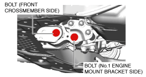
1. Loosen the bolts shown in the figure.
am3zzw00017186
|
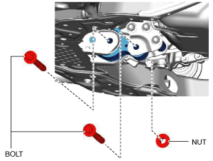
2. Remove the bolts shown in the figure.
am3zzw00017187
|
3. Remove the No.1 engine mount rubber.
No.1 Engine Mount Installation Note
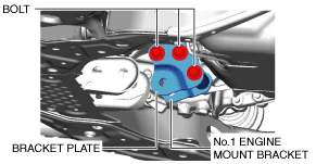
1. Install the No.1 engine mount bracket and bracket plate, and temporarily tighten the bolts shown in the figure.
am3zzw00017188
|
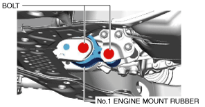
2. Install the No.1 engine mount rubber, and temporarily tighten the bolts shown in the figure.
am3zzw00017189
|
3. Tighten the No.1 engine mount bracket and bracket plate installation bolts in the order shown in the figure.
am3zzw00017190
|
4. Tighten the No.1 engine mount rubber installation bolts shown in the figure.
am3zzw00017191
|
Tightening torque
|
Installation position |
Tightening torque |
|---|---|
|
No.1 engine mount bracket side
|
130—151 N·m {14—15 kgf·m, 96—111 ft·lbf}
|
|
Front crossmember side
|
130—164 N·m {14—16 kgf·m, 96—120 ft·lbf}
|
No.3 Engine Mount
1. Disconnect the negative battery cable. (See NEGATIVE BATTERY CABLE DISCONNECTION/CONNECTION [SKYACTIV-D 1.5].)
2. Remove the engine cover. (See ENGINE COVER REMOVAL/INSTALLATION [SKYACTIV-D 1.5].)
3. Remove in the order indicated in the table.
4. Install in the reverse order of removal.
am3zzw00017192
|
|
1
|
No.3 engine mount
|
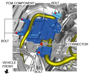
No.3 engine mount removal note
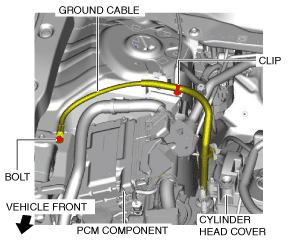
1. Remove the clip and bolt shown in the figure and set the ground cable aside.
am3zzw00017193
|
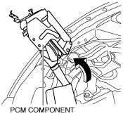
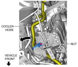
2. Set the PCM component aside using the following procedure:
am3zzw00017194
|
am3zzw00017195
|
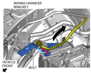
3. Set the wiring harness bracket aside using the following procedure:
am3zzw00017196
|
am3zzw00017197
|
4. Remove the front under cover No.2. (See FRONT UNDER COVER No.2 REMOVAL/INSTALLATION.)
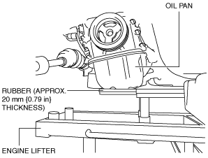
5. Remove the seal plate installed to the underside of the oil pan. (See OIL PAN REMOVAL/INSTALLATION [SKYACTIV-D 1.5].)
6. Before removing the No.3 engine mount, support the engine (oil pan) using a commercially available engine lifter or garage jack.
am3uuw00008905
|
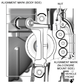
7. Place alignment marks on the locations shown in the figure so that they can be assembled to the same positions as before removal.
am3zzw00017198
|
8. Remove the No.3 engine mount.
No.3 engine mount installation note
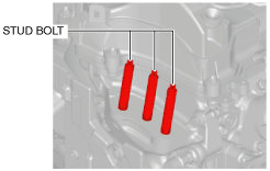
1. Tighten the engine front cover stud bolts.
ac3wzw00001751
|
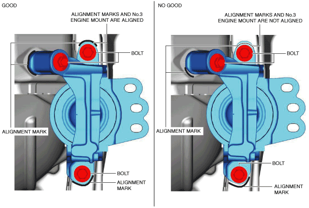
2. Temporarily tighten the No.3 engine mount installation bolts and nuts using the following procedure:
am3zzw00017199
|
am3zzw00017200
|
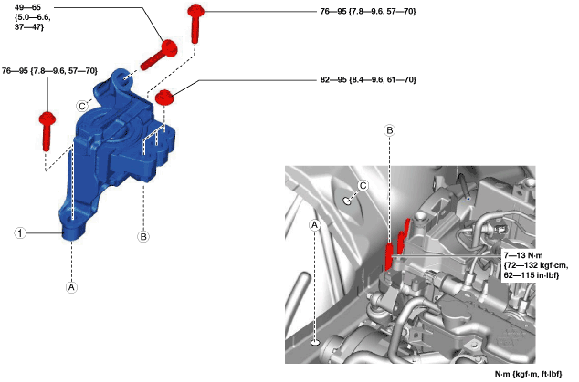
3. Tighten the No.3 engine mount installation bolts and nuts in the order shown in the figure.
am3zzw00017201
|
Tightening torque
|
Installation position |
Tightening torque |
|---|---|
|
1
|
76—95 N·m {7.8—9.6 kgf·m, 57—70 ft·lbf}
|
|
2
|
82—95 N·m {8.4—9.6 kgf·m, 61—70 ft·lbf}
|
|
3
|
49—65 N·m {5.0—6.6 kgf·m, 37—47 ft·lbf}
|
4. Remove the engine lifter or garage jack.
5. Install in the reverse order of removal.
No.4 Engine Mount
1. Disconnect the negative battery cable. (See NEGATIVE BATTERY CABLE DISCONNECTION/CONNECTION [SKYACTIV-D 1.5].)
2. Remove the air cleaner, air hose and fresh-air duct. (See INTAKE-AIR SYSTEM REMOVAL/INSTALLATION [SKYACTIV-D 1.5].)
3. Remove the battery and battery tray. (See BATTERY REMOVAL/INSTALLATION [SKYACTIV-D 1.5].)
4. Remove in the order indicated in the table.
5. Install in the reverse order of removal.
am3zzw00017202
|
|
1
|
No.4 engine mount rubber
|
|
2
|
No.4 engine mount bracket
|
No.4 engine mount rubber removal note
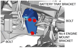
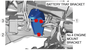
1. Remove the battery tray bracket.
am3zzw00017203
|
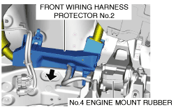
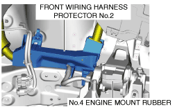
2. Set the front wiring harness protector No.2 aside from the body. (See RELAY AND FUSE BLOCK REMOVAL/INSTALLATION.)
am3zzw00017204
|
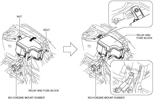
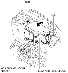
3. Remove the bolt and nut shown in the figure and set the relay and fuse block aside.
am3zzw00017205
|
4. Remove the front under cover No.2. (See FRONT UNDER COVER No.2 REMOVAL/INSTALLATION.)
ac5uuw00000661
|
ac5uuw00000662
|
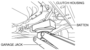
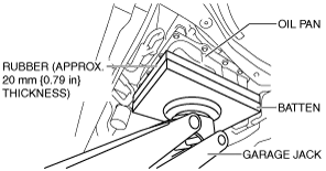
5. Before removing the No.4 engine mount rubber, support the transaxle using a commercially available engine lifter or garage jack.
6. Remove the No.4 engine mount rubber.
No.4 engine mount bracket removal note
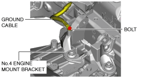
1. Remove the bolt shown in the figure and set the ground cable aside.
am3zzw00017206
|
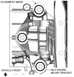
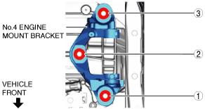
2. Place alignment marks on the locations shown in the figure so that they can be assembled to the same positions as before removal.
am3zzw00017207
|
3. Remove the No.4 engine mount bracket.
No.4 engine mount bracket installation note
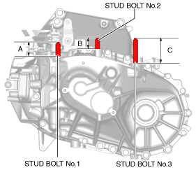
1. Measure the projection of the transaxle stud bolts. (MTX)
ac3wzw00001157
|
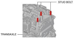
2. Tighten the transaxle stud bolts. (ATX)
ac3wzw00000647
|
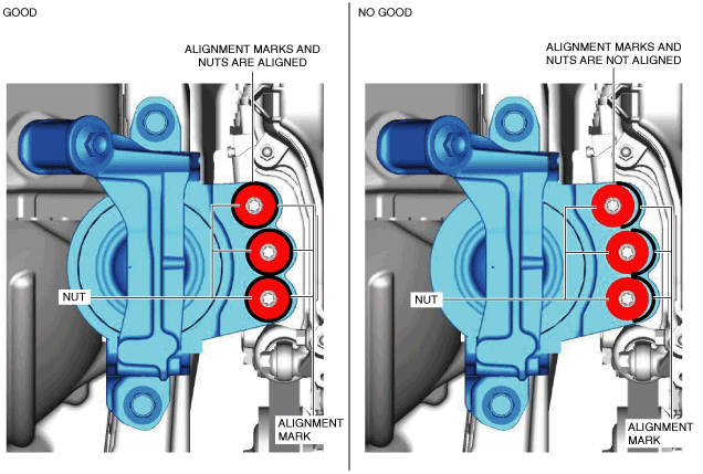
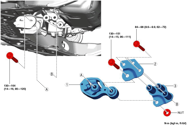
3. Align the alignment marks on the No.4 engine mount bracket and nuts, and temporarily tighten the nuts shown in the figure.
am3zzw00017208
|
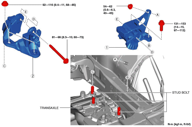
4. Tighten the No.4 engine mount bracket installation nuts in the order shown in the figure.
am3zzw00017209
|
5. Install the ground cable to the No.4 engine mount bracket.
am3zzw00017206
|
No.4 engine mount rubber installation note
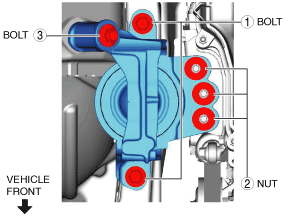
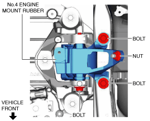
1. Install the No.4 engine mount rubber and temporarily tighten the bolts and nut shown in the figure.
am3zzw00017210
|
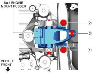
2. Tighten the No.4 engine mount rubber installation bolts and nut in the order shown in the figure.
am3zzw00017211
|
Tightening torque
|
Installation position |
Tightening torque |
|---|---|
|
1, 2
|
131—153 N·m {14—15 kgf·m, 97—112 ft·lbf}
|
|
3
|
54—62 N·m {5.6—6.3 kgf·m, 40—45 ft·lbf}
|
|
4
|
81—99 N·m {8.3—10 kgf·m, 60—73 ft·lbf}
|
3. Remove the engine lifter or garage jack.
4. Install the front under cover No.2. (See FRONT UNDER COVER No.2 REMOVAL/INSTALLATION.)
5. Install the relay and fuse block using the following procedure:
am3zzw00017212
|
6. Install the wiring harness protector No.2. (See RELAY AND FUSE BLOCK REMOVAL/INSTALLATION.)
am3zzw00017213
|
7. Install the battery tray bracket in the order shown in the figure.
am3zzw00017214
|