 |
am3zzw00017392
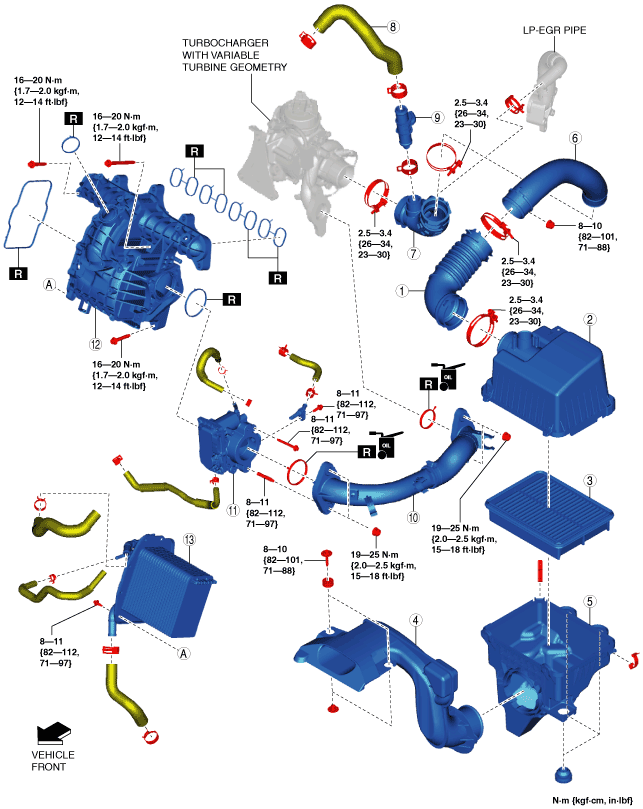
INTAKE-AIR SYSTEM REMOVAL/INSTALLATION [SKYACTIV-D 1.5]
id0113q2801900
1. Disconnect the negative battery cable. (See NEGATIVE BATTERY CABLE DISCONNECTION/CONNECTION [SKYACTIV-D 1.5].)
2. Remove in the order shown in the figure.
3. Install in the reverse order of removal.
am3zzw00017392
|
|
1
|
Air hose
(See Air Hose Installation Note.)
|
|
2
|
Air cleaner cover
|
|
3
|
Air cleaner element
|
|
4
|
Fresh-air duct
(See Fresh-air Duct Removal Note.)
|
|
5
|
Air cleaner case
|
|
6
|
Air inlet pipe
|
|
7
|
Turbocharger air inlet hose
|
|
8
|
Breather hose
|
|
9
|
Blow-by heater
|
|
10
|
Turbocharger air outlet pipe
|
|
11
|
Intake shutter valve
|
|
12
|
Intake manifold
(See Intake Manifold Removal Note.)
|
|
13
|
Water-cooled charge air cooler
|
Air Cleaner Cover Removal Note
1. Remove the MAF sensor/IAT sensor No.1. (See MASS AIR FLOW (MAF) SENSOR/INTAKE AIR TEMPERATURE (IAT) SENSOR NO.1 REMOVAL/INSTALLATION [SKYACTIV-D 1.5].)
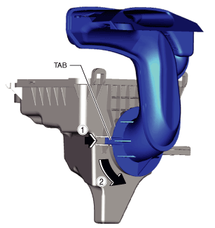
Fresh-air Duct Removal Note
1. Remove the following parts as a single unit:
2. While moving the tabs in the direction shown in the figure, rotate the fresh-air duct.
am3zzw00017393
|
3. Remove the fresh-air duct.
Turbocharger Air Inlet Hose Removal Note
1. Remove the battery and the battery tray. (See BATTERY REMOVAL/INSTALLATION [SKYACTIV-D 1.5].)
2. Disconnect the blow-by heater connector.
3. Remove the following parts as a single unit:
4. Remove the turbocharger air inlet hose.
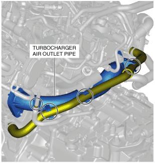
Turbocharger Air Outlet Pipe Removal Note
1. Detach the hose and hose clip shown in the figure.
am2zzw00012050
|
2. Remove the turbocharger air outlet pipe.
Intake Manifold Removal Note
1. Remove the engine coolant reserve tank. (See ENGINE COOLANT RESERVE TANK REMOVAL/INSTALLATION [SKYACTIV-D 1.5].)
2. Remove the EGR pipe. (See EGR PIPE REMOVAL/INSTALLATION [SKYACTIV-D 1.5].)
3. Remove the HP-EGR pipe. (See HP-EGR CONTROL VALVE REMOVAL/INSTALLATION [SKYACTIV-D 1.5].)
4. Remove the front under cover No.2. (See FRONT UNDER COVER No.2 REMOVAL/INSTALLATION.)
5. Drain the water-cooled charge air cooler coolant. (See WATER-COOLED CHARGE AIR COOLER COOLANT REPLACEMENT [SKYACTIV-D 1.5].)
6. Remove the water-cooled charge air cooler reserve tank. (See WATER-COOLED CHARGE AIR COOLER RESERVE TANK REMOVAL/INSTALLATION [SKYACTIV-D 1.5].)
7. Disconnect the connectors of the following parts: (The sensor unit is not removed. )
8. Disconnect the wiring harness clip installed to the intake manifold.
9. Remove the intake manifold.
Intake Manifold Installation Note
1. Install the intake manifold.
2. Connect the wiring harness clip installed to the intake manifold.
3. Connect the connectors of the following parts:
4. Install the water-cooled charge air cooler reserve tank. (See WATER-COOLED CHARGE AIR COOLER RESERVE TANK REMOVAL/INSTALLATION [SKYACTIV-D 1.5].)
5. Refill the water-cooled charge air cooler coolant. (See WATER-COOLED CHARGE AIR COOLER COOLANT REPLACEMENT [SKYACTIV-D 1.5].)
6. Install the front under cover No.2. (See FRONT UNDER COVER No.2 REMOVAL/INSTALLATION.)
7. Install the EGR pipe. (See EGR PIPE REMOVAL/INSTALLATION [SKYACTIV-D 1.5].)
8. Install the HP-EGR pipe. (See HP-EGR CONTROL VALVE REMOVAL/INSTALLATION [SKYACTIV-D 1.5].)
9. Install the engine coolant reserve tank. (See ENGINE COOLANT RESERVE TANK REMOVAL/INSTALLATION [SKYACTIV-D 1.5].)
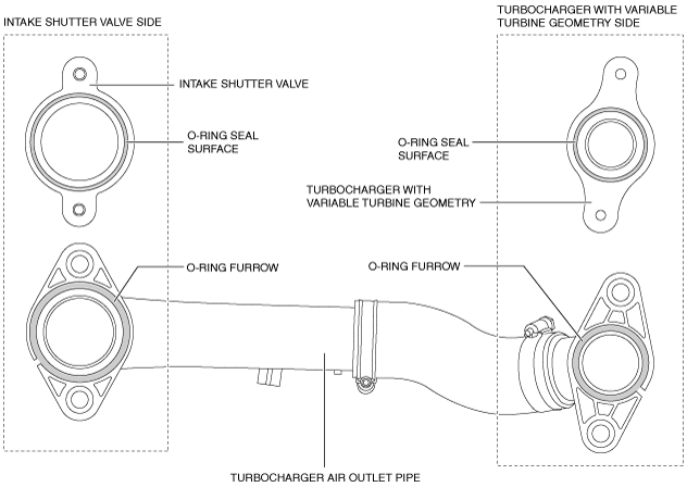
Turbocharger Air Outlet Pipe Installation Note
1. Remove foreign matter (sand or dust) on the seal surfaces of the variable geometry turbocharger and intake shutter valve O-ring, and the grooved area of the O-ring of the turbocharger air outlet pipe.
am2zzw00012051
|
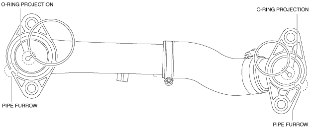
2. Apply engine oil to the entire surface of the O-ring.
3. Align the O-ring projection with the pipe furrow and install the O-ring.
am2zzw00012052
|
4. Install the turbocharger air outlet pipe.
5. Connect the hose and hose clip as shown in the figure.
am2zzw00012050
|
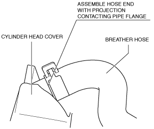
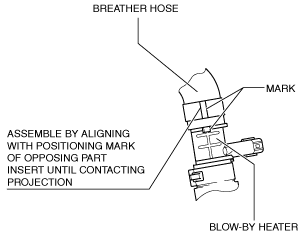
Breather Hose Installation Note
1. Install the breather hose as shown in the figure.
Cylinder head cover side
am2zzw00012053
|
Blow-by heater side
am2zzw00012054
|
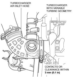
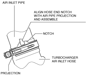
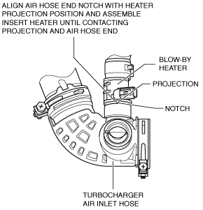
Turbocharger Air Inlet Hose Installation Note
1. Install the turbocharger air inlet hose as shown in the figure.
Turbocharger with variable turbine geometry side
am2zzw00012055
|
Air inlet pipe side
am2zzw00012056
|
Blow-by heater side
am2zzw00012057
|
2. Install the following parts as a single unit:
3. Connect the blow-by heater connector.
4. Install the battery and the battery tray. (See BATTERY REMOVAL/INSTALLATION [SKYACTIV-D 1.5].)
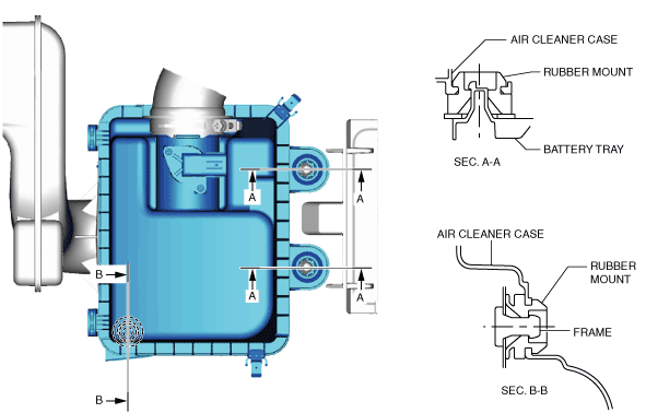
Air Cleaner Case Installation Note
1. Install the air cleaner case as shown in the figure.
am3zzw00017394
|
Fresh-air Duct Installation Note
1. Install the fresh-air duct to the air cleaner case.
2. Install the fresh-air duct and air cleaner case as a single unit.
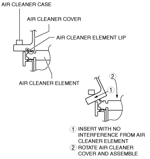
Air Cleaner Cover Installation Note
1. Install the air cleaner cover as shown in the figure.
am2zzw00012059
|
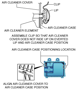
2. Install the air cleaner cover and air cleaner case for clip as shown in the figure.
am3zzw00017395
|
3. Install the MAF sensor/IAT sensor No.1. (See MASS AIR FLOW (MAF) SENSOR/INTAKE AIR TEMPERATURE (IAT) SENSOR NO.1 REMOVAL/INSTALLATION [SKYACTIV-D 1.5].)
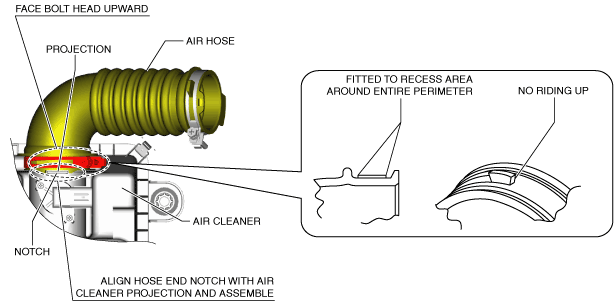
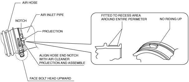
Air Hose Installation Note
1. Install the air hose as shown in the figure.
Air cleaner side
am3zzw00017396
|
Air inlet pipe side
am2zzw00012062
|