STEERING WHEEL AND COLUMN REMOVAL/INSTALLATION
id061300801400
-
Warning
-
• The steering column (EPS motor) temperature increases directly after continuous turning of the steering mechanism which could cause burns if it is touched. Before performing any servicing, verify that the steering column has cooled off.
-
Caution
-
• If the EPS CM configuration is not completed, the EPS will not operate properly. If the EPS CM is replaced, always use the automatic configuration function so that the EPS operation conditions are correct.
• If the EPS column is dropped it could result in internal damage to the EPS CM, therefore be careful not to drop it. Replace the EPS CM if it is subjected to an impact.
-
Note
-
• When the ignition is switched ON or the engine is started after the EPS CM has been replaced, the EPS CM reads data from the instrument cluster via CAN communication to perform automatic configuration.
• The EPS CM prior to replacement stores the vehicle specification information.
• A new EPS CM does not store any vehicle specification information.
1. Remove the following parts:
- (1) Upper panel (See UPPER PANEL REMOVAL.) (See UPPER PANEL INSTALLATION.)
-
- (2) Rear console (See REAR CONSOLE REMOVAL/INSTALLATION.)
-
- (3) Shift lever knob (MTX) (See MANUAL TRANSAXLE SHIFT MECHANISM REMOVAL/INSTALLATION [F35M-R].) (See MANUAL TRANSAXLE SHIFT MECHANISM REMOVAL/INSTALLATION [C66M-R].) (See MANUAL TRANSAXLE SHIFT MECHANISM REMOVAL/INSTALLATION [D66M-R].) (See MANUAL TRANSAXLE SHIFT MECHANISM REMOVAL/INSTALLATION [F66M-R].)
-
- (4) Selector lever knob (ATX) (See AUTOMATIC TRANSAXLE SHIFT MECHANISM REMOVAL/INSTALLATION.)
-
- (5) Shift panel (See SHIFT PANEL REMOVAL/INSTALLATION.)
-
- (6) Front console box (See FRONT CONSOLE BOX REMOVAL/INSTALLATION.)
-
- (7) CD player (with CD player) (See CD PLAYER REMOVAL.) (See CD PLAYER INSTALLATION.)
-
- (8) DVD/CD player (with DVD/CD player) (See DVD/CD PLAYER REMOVAL.) (See DVD/CD PLAYER INSTALLATION.)
-
- (9) Side wall (See SIDE WALL REMOVAL/INSTALLATION.)
-
- (10) Glove compartment (See GLOVE COMPARTMENT REMOVAL/INSTALLATION.)
-
- (11) Decoration panel (See DECORATION PANEL REMOVAL/INSTALLATION.)
-
- (12) Front console (See FRONT CONSOLE REMOVAL/INSTALLATION.)
-
- (13) Driver-side front scuff plate (See FRONT SCUFF PLATE REMOVAL/INSTALLATION.)
-
- (14) Driver-side front side trim (See FRONT SIDE TRIM REMOVAL/INSTALLATION.)
-
- (15) Bonnet release lever (See BONNET RELEASE LEVER AND RELEASE CABLE REMOVAL/INSTALLATION.)
-
- (16) Fuel-filler lid opener lever (See FUEL-FILLER LID OPENER AND LEVER REMOVAL/INSTALLATION.)
-
- (17) Lower panel (See LOWER PANEL REMOVAL/INSTALLATION.)
-
- (18) AudioPilot®2 microphone (with Bose®) (See AudioPilot®2 MICROPHONE REMOVAL/INSTALLATION.)
-
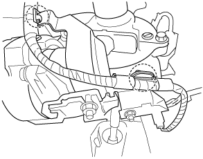
2. Detach the harness clips shown in the figure.
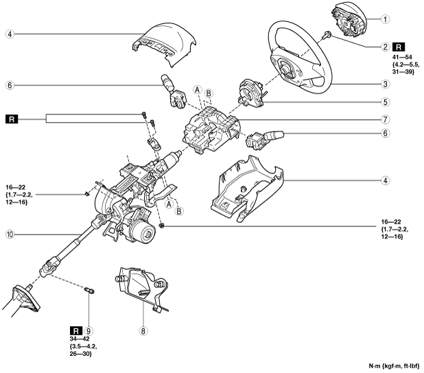
3. Remove in the order indicated in the table.
4. Install in the reverse order of removal.
5. If the EPS CM is replaced, perform the following procedure.
- (1) After installation, switch the ignition ON or start the engine, and maintain this condition for approx. 1 min to allow the EPS CM automatic configuration to be performed.
-
- (2) Switch the ignition OFF, and maintain this condition for approx. 3 s
-
- (3) Switch the ignition ON (engine on or off) to allow the EPS CM automatic configuration to be performed.
-
- (4) Clear the DTC from the memory. (See ELECTRIC POWER STEERING (EPS) ON-BOARD DIAGNOSIS.)
-
|
1
|
Driver-side air bag module
|
|
2
|
Lockbolt
|
|
3
|
Steering wheel
|
|
4
|
Column cover
|
|
5
|
Clock spring
|
|
6
|
Light switch, wiper and washer switch
|
|
7
|
Start stop unit
|
|
8
|
Joint cover
|
|
9
|
Joint bolt
|
|
10
|
Steering column component
|
|
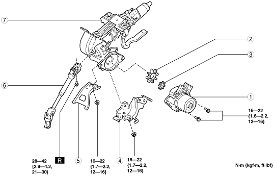
1
|
EPS CM
|
|
2
|
Rubber
|
|
3
|
Spacer
|
|
4
|
Harness bracket
|
|
5
|
Bracket (MTX vehicles)
|
|
6
|
Intermediate shaft
|
|
7
|
Steering column
|
Steering Wheel Removal Note
-
Caution
-
• Do not try to remove the steering wheel by hitting the shaft with a hammer. The steering column will be damaged.
1. Set the vehicle wheels in the straight-ahead position.
2. Remove the steering wheel using any commercially available puller.
Steering Column Component Removal Note
-
Caution
-
• Always lock the adjusting lever to prevent damage to the steering column. In addition, do not unlock the adjusting lever until the steering column installation is completed.
• If the steering column is removed, remove it according to the procedure to prevent damage to intermediate shaft that could result if the steering column is removed in the incorrect order.
1. Lock the adjusting lever.
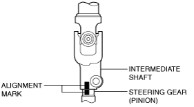
2. Place alignment marks on the steering gear (pinion) and the intermediate shaft as shown in the figure.
3. Remove the bolt, disconnect the intermediate shaft from the steering gear (pinion shaft).
4. Remove the nut, and then remove the steering column component from the dashboard member.
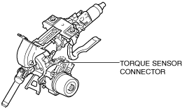
EPS CM Removal Note
1. Disconnect the torque sensor connector (EPS CM side).
2. Remove the EPS CM.
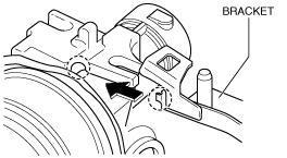
Bracket Installation Note
1. Insert the bracket bolt into the steering column and install the projecting part of the bracket to the installation area of the steering column.
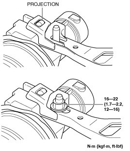
2. Verify that the projection on the steering column is inserted into the hole in the bracket as shown in the figure and tighten the nut to the specified torque.
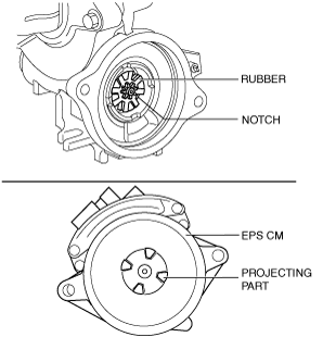
Spacer, Rubber and EPS CM Installation Note
1. Install the spacer and rubber to the steering column.
2. Install the EPS CM so that the projecting part of the EPS CM (rotor) is engaged with the notch in the rubber.
-
Note
-
• If the projecting part of the EPS CM (rotor) is not engaged with the notch in the rubber, adjust the position of the EPS CM projection (rotor).
Steering Column Component Installation Note
-
Caution
-
• If the steering column is installed, install it according to the procedure to prevent damage to intermediate shaft that could result if the steering column is installed in the incorrect order.
• Do not unlock the adjusting lever until the steering column installation is completed to prevent damage to the steering column.
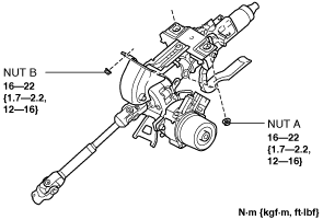
1. Temporarily install the steering column component to the dashboard member using nuts A and B.
2. Tilt the steering column component towards the temporarily installed nut B and temporarily install the steering column component to the instrument panel member using nut A
3. Tighten the nuts in the order of nut A and nut B.
4. Align the alignment marks on the steering column and the steering gear (pinion), which were placed before removing the intermediate shaft, and install the intermediate shaft.
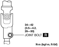
5. Tighten a new joint bolt.
-
Note
-
• Verify that joint bolt is installed to the groove of the steering gear (pinion).
Steering Wheel Installation Note
1. Set the vehicle wheels in the straight-ahead position, and install the steering wheel using a new lockbolt.