MANUAL TRANSAXLE SHIFT MECHANISM REMOVAL/INSTALLATION [F66M-R]
id0516n2160800
Removal
1. Disconnect the negative battery cable. (See NEGATIVE BATTERY CABLE DISCONNECTION/CONNECTION [SKYACTIV-G 1.5, SKYACTIV-G 2.0, SKYACTIV-G 2.5].)
2. Remove the shift lever using the following procedure:
- (1) Remove the upper panel. (See UPPER PANEL REMOVAL.)
-
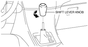
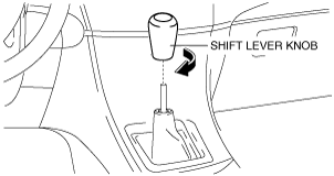
- (2) Remove the shift lever knob.
-
- (3) Remove the shift panel. (See SHIFT PANEL REMOVAL/INSTALLATION.)
-
- (4) Remove the front console box. (See FRONT CONSOLE BOX REMOVAL/INSTALLATION.)
-
- (5) Remove the side wall. (See SIDE WALL REMOVAL/INSTALLATION.)
-
- (6) Remove the rear console. (See REAR CONSOLE REMOVAL/INSTALLATION.)
-
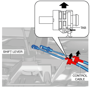
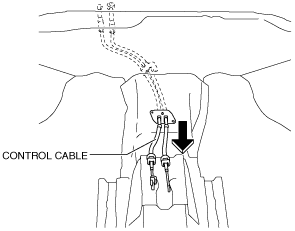
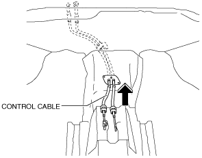
- (7) Press the tabs on the control cable as shown in the figure and disconnect the control cable from the shift lever.
-
-
Caution
-
• When disconnecting the control cable from the shift lever, do not press the control cable tabs with excessive force. Otherwise, they may be damaged.
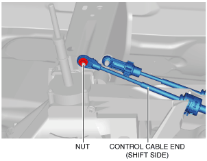
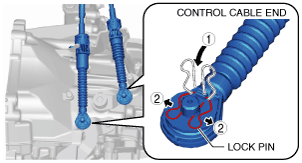
- (8) Disconnect the control cable end (shift side) from the shift lever as shown in the figure.
-
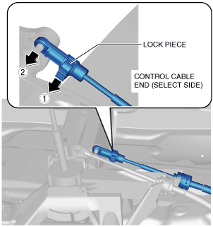
- (9) Disconnect the control cable end (select side) from the shift lever using the following procedure:
-
-
Caution
-
• When pressing the lock piece out of the control cable end (selector side), do not press out the lock piece with excessive force. Otherwise, it may be damaged.
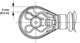
- 1) Push out the lock piece in the direction shown in the figure.
-
- 2) Disconnect the control cable end (select side) from the shift lever.
-
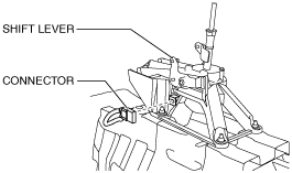
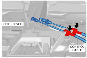
- (10) Disconnect the connector from the shift lever as shown in the figure.
-
- (11) Remove the shift lever.
-
3. Remove the control cable using the following procedure:
- (1) Remove the air cleaner and air hose as a single unit. (See INTAKE-AIR SYSTEM REMOVAL/INSTALLATION [SKYACTIV-G 1.5, SKYACTIV-G 2.0, SKYACTIV-G 2.5].)
-
- (2) Remove the battery tray and PCM component. (See BATTERY REMOVAL/INSTALLATION [SKYACTIV-G 1.5, SKYACTIV-G 2.0, SKYACTIV-G 2.5].)
-
- (3) Disconnect the control cable ends from the MTX using the following procedure.
-
-
Caution
-
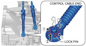
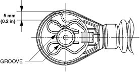
• Pull the lock pin within the range shown in the figure. If the lock pin is pulled excessively, it could deform and no longer function.
- 1) Pull the lock pin in the direction of the arrow shown in the figure and release the control cable end (MTX side) lock.
-
- 2) Disconnect the control cable ends from the MTX.
-
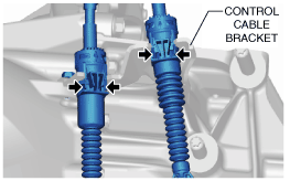
- (4) Press the tabs on the control cable and disconnect the control cable from the bracket.
-
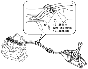
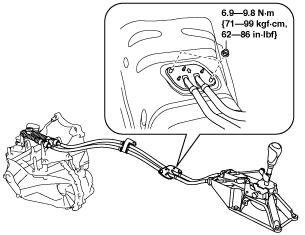
- (5) Remove the fastening nut for the control cable.
-
- (6) Remove the fastening nuts for the grommet.
-
- (7) Remove the control cable.
-
4. Make sure that the shift lever (transaxle side) is in neutral position.
Installation
1. Make sure that the MTX is in neutral position.
2. Install the control cable using the following procedure:
- (1) Install the control cable.
-
- (2) Install the fastening nuts for the grommet.
-
- (3) Install the fastening nut for the control cable.
-
- (4) Connect the control cable to the bracket.
-
- (5) Connect the control cable ends to the MTX using the following procedure.
-
-
Caution
-
• Pull the lock pin within the range shown in the figure. If the lock pin is pulled excessively, it could deform and no longer function.
- 1) Install the lock pin to the groove of the control cable ends.
-
- 2) Connect the control cable end to the MTX.
-
- (6) Install the battery tray and PCM component. (See BATTERY REMOVAL/INSTALLATION [SKYACTIV-G 1.5, SKYACTIV-G 2.0, SKYACTIV-G 2.5].)
-
- (7) Install the air cleaner and air hose as a single unit. (See INTAKE-AIR SYSTEM REMOVAL/INSTALLATION [SKYACTIV-G 1.5, SKYACTIV-G 2.0, SKYACTIV-G 2.5].)
-
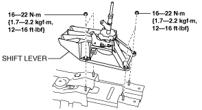
3. Install the shift lever using the following procedure:
- (1) Install the shift lever.
-
- (2) Connect the connector to the shift lever as shown in the figure.
-
- (3) Connect the control cable to the shift lever.
-
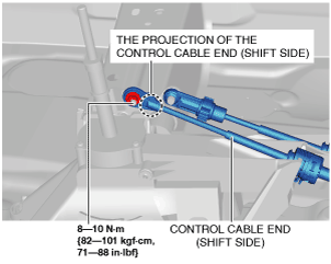
- (4) Install the control cable end (shift side) to the shift lever so that the projection of the control cable end (shift side) is positioned towards the upper side of the vehicle.
-
- (5) Use the following procedure to install the control cable end (selector side) to the shift lever.
-
-
Note
-
• Because the vehicle may have been moved during the servicing, verify that the shift lever is in neutral again.
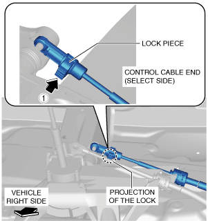
- 1) Install the control cable end (selector side) to the shift lever so that the projection of the lock piece is positioned on the right side of the vehicle.
-
- 2) Verify that the shift lever and the manual transaxle are in the neutral position.
-
- 3) Shift the shift lever to fourth gear.
-
- 4) Press in the lock piece in the direction shown in the figure. (1 in Fig.)
-
- 5) Shift the shift lever to the neutral position.
-
- (6) Install the rear console. (See REAR CONSOLE REMOVAL/INSTALLATION.)
-
- (7) Install the side wall. (See SIDE WALL REMOVAL/INSTALLATION.)
-
- (8) Install the front console box. (See FRONT CONSOLE BOX REMOVAL/INSTALLATION.)
-
- (9) Install the shift panel. (See SHIFT PANEL REMOVAL/INSTALLATION.)
-
- (10) Install the shift lever knob.
-
- (11) Install the upper panel. (See UPPER PANEL INSTALLATION.)
-
4. Connect the negative battery cable. (See NEGATIVE BATTERY CABLE DISCONNECTION/CONNECTION [SKYACTIV-G 1.5, SKYACTIV-G 2.0, SKYACTIV-G 2.5].)