 |
am3zzw00014733
BATTERY REMOVAL/INSTALLATION [SKYACTIV-G 1.5, SKYACTIV-G 2.0, SKYACTIV-G 2.5]
id0117i6800500
Operation After Replacing Battery (With i-stop)
|
Step |
Action |
|---|---|
|
1
|
Switch the ignition ON (engine off).
|
|
2
|
Shift the selector lever to the N position. (ATX)
Shift the shift lever to the neutral position. (MTX)
|
|
3
|
Perform the following work with the brake pedal depressed.
1. Depress the accelerator pedal for 5 s or more.
2. Verify that the charging system warning light and the master warning light flash.
3. Depress and release the accelerator pedal 3 times.
4. Verify that the charging system warning light illuminates and the master warning light turns off.
|
|
4
|
Switch the ignition off and disconnect the negative battery cable. (See NEGATIVE BATTERY CABLE DISCONNECTION/CONNECTION [SKYACTIV-G 1.5, SKYACTIV-G 2.0, SKYACTIV-G 2.5].)
|
|
5
|
Verifying battery condition initialization setting (i-stop setting). (See BATTERY CONDITION INITIALIZATION SETTING (i-stop SETTING) [SKYACTIV-G 1.5, SKYACTIV-G 2.0, SKYACTIV-G 2.5].)
|
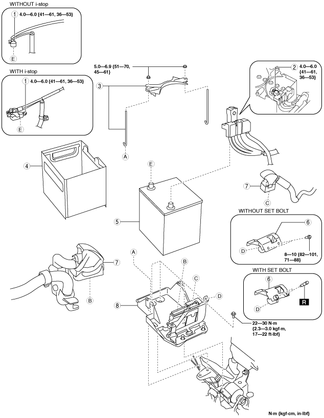
Battery Removal/Installation
1. Remove in the order indicated in the table.
2. Install in the reverse order of removal.
am3zzw00014733
|
|
1
|
Negative battery cable
|
|
2
|
Positive battery cable
|
|
3
|
Battery clamp
|
|
4
|
Battery box
|
|
5
|
Battery
(See Battery removal note.)
|
|
6
|
PCM cover
|
|
7
|
PCM connector
|
|
8
|
Battery tray and PCM component
|
Battery removal note
Battery tray and PCM component removal note
1. Remove the air cleaner, air hose and fresh air duct component. (See INTAKE-AIR SYSTEM REMOVAL/INSTALLATION [SKYACTIV-G 1.5, SKYACTIV-G 2.0, SKYACTIV-G 2.5].)
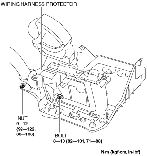
2. Remove the bolt and nut securing the wiring harness protector to the battery tray.
am3zzw00014734
|
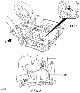
3. Remove the three battery tray bolts so that the battery tray is free to move.
4. Release the wiring harness clips at the three locations shown in the figure and remove the battery tray and PCM component.
ac5wzw00003083
|
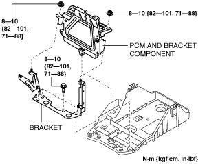
5. When replacing the battery tray with a new one, perform the following procedure:
ac5wzw00002656
|
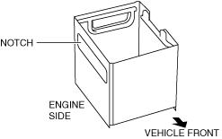
Battery box installation note
1. Install the battery box so that the side with the larger notch is pointed at the engine side.
am3zzw00015052
|