 |
am3zzw00013764
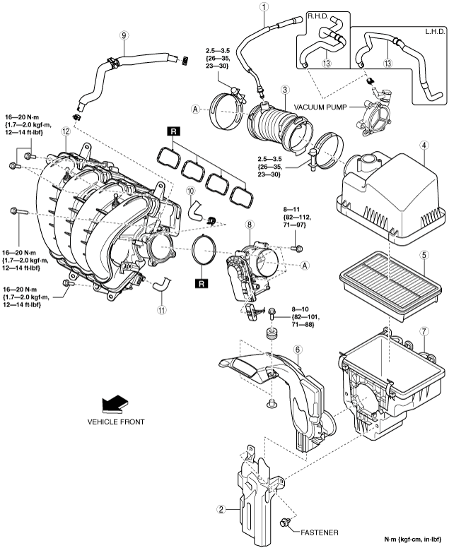
INTAKE-AIR SYSTEM REMOVAL/INSTALLATION [SKYACTIV-G 1.5, SKYACTIV-G 2.0, SKYACTIV-G 2.5]
id0113zc801900
1. Disconnect the negative battery cable. (See NEGATIVE BATTERY CABLE DISCONNECTION/CONNECTION [SKYACTIV-G 1.5, SKYACTIV-G 2.0, SKYACTIV-G 2.5].)
2. Remove in the order indicated in the table.
3. Install in the reverse order of removal.
am3zzw00013764
|
|
1
|
Ventilation hose
|
|
2
|
Resonance chamber
|
|
3
|
Air hose
|
|
4
|
Air cleaner cover
|
|
5
|
Air cleaner element
|
|
6
|
Fresh-air duct
(See Fresh-air Duct Removal Note.)
|
|
7
|
Air cleaner case
|
|
8
|
Throttle body
|
|
9
|
Vacuum hose (between intake manifold and vacuum pump)
|
|
10
|
Evaporative hose
|
|
11
|
PCV hose
|
|
12
|
Intake manifold
|
|
13
|
Vacuum hose (between vacuum pump and power brake unit)
|
Resonance Chamber Removal Note
1. Remove the MAF sensor/IAT sensor No.1. (See MASS AIR FLOW (MAF) SENSOR/INTAKE AIR TEMPERATURE (IAT) SENSOR NO.1 REMOVAL/INSTALLATION [SKYACTIV-G 1.5, SKYACTIV-G 2.0, SKYACTIV-G 2.5].)
2. Remove the following parts as a single unit:
3. Remove the resonance chamber.
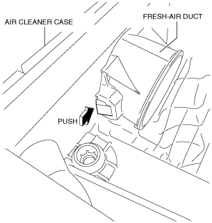
Fresh-air Duct Removal Note
1. Pull out the fresh-air duct while pressing the tab shown in the figure.
am3uuw00011105
|
Vacuum Hose (Between Intake Manifold and Vacuum Pump) Removal Note
1. Remove the plug hole plate. (See PLUG HOLE PLATE REMOVAL/INSTALLATION [SKYACTIV-G 1.5, SKYACTIV-G 2.0, SKYACTIV-G 2.5].)
2. Remove the vacuum hose (between intake manifold and vacuum pump).
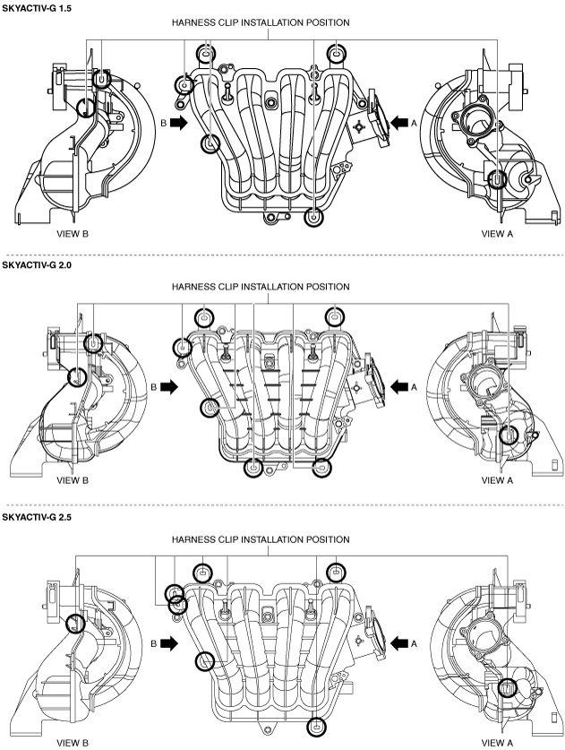
Intake Manifold Removal Note
1. Disconnect the MAP sensor/IAT sensor No.2 connector. (See MANIFOLD ABSOLUTE PRESSURE (MAP) SENSOR/INTAKE AIR TEMPERATURE (IAT) SENSOR NO.2 REMOVAL/INSTALLATION [SKYACTIV-G 1.5, SKYACTIV-G 2.0, SKYACTIV-G 2.5].)
2. Disconnect the harness clip from the intake manifold as shown in the figure.
am3zzw00013765
|
3. Remove the intake manifold.
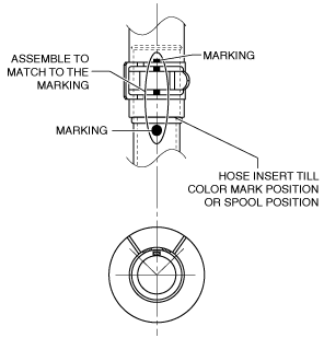
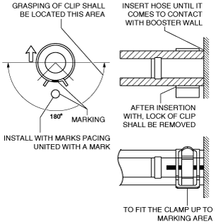
Vacuum Hose (Between Vacuum Pump and Power Brake Unit) Installation Note
1. Install the vacuum hose (between vacuum pump and power brake unit) as shown in the figure.
Vacuum pump side
am3zzw00017400
|
Power brake unit side
am3zzw00017401
|
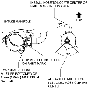
Evaporative Hose Installation Note
1. Install the evaporative hose as shown in the figure.
am3zzw00017402
|
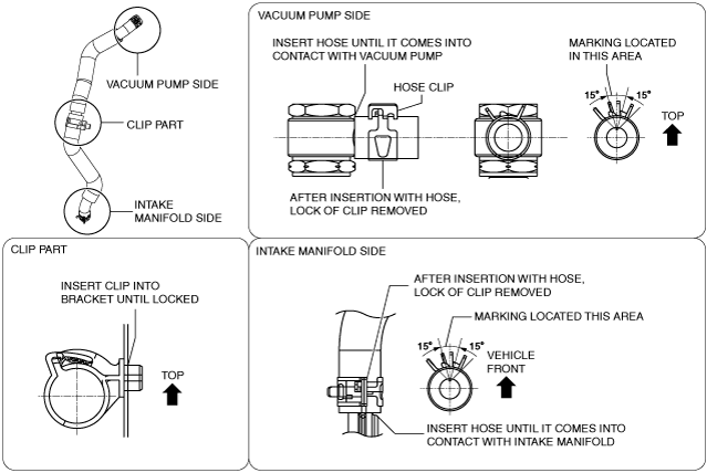
Vacuum Hose (Between Intake Manifold and Vacuum Pump) Installation Note
1. Install the vacuum hose (between intake manifold and vacuum pump) as shown in the figure.
am3uuw00011110
|
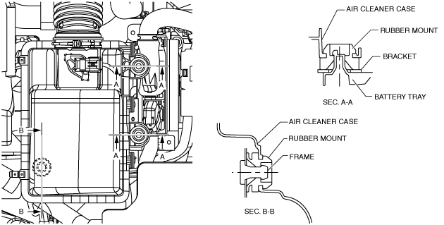
Air Cleaner Case Installation Note
1. Install the air cleaner case as shown in the figure.
am3uuw00011111
|
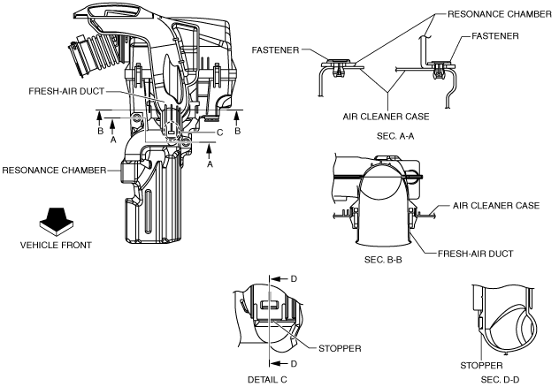
Fresh-air Duct Installation Note
1. Install the fresh-air duct as shown in the figure.
am3uuw00011112
|
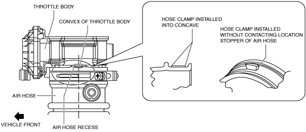
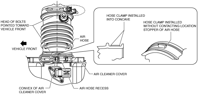
Air Hose Installation Note
1. Install the air hose as shown in the figure.
Throttle body side
am3zzw00016749
|
Air cleaner side
am3zzw00016750
|
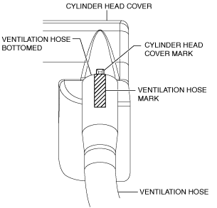
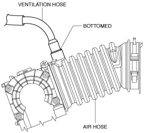
Ventilation Hose Installation Note
1. Install the ventilation hose as shown in the figure.
Cylinder head cover side
am3uuw00011115
|
Air hose side
am3uuw00011116
|