START STOP UNIT REMOVAL/INSTALLATION


id091400110300

Caution
•  Never remove bolts and screws other than the bolt in Steps 8 and 9. Otherwise, it will cause internal damage and the steering lock cannot be unlocked, resulting in the inability to perform the start-stop unit removal/installation.
•  If configuration is not performed when the start stop unit is replaced with a new one, the vehicle specification information is not stored in the start stop unit and the system will not operate normally.
•  When performing configuration, it is necessary to read the vehicle specification information from the start stop unit before replacing it. Connect the M-MDS to the vehicle and perform vehicle identification before removing the start stop unit. The vehicle specification information is temporarily stored in the M-MDS.
Note
•  The start stop unit prior to replacement stores the vehicle specification information.
•  A new start stop unit does not store any vehicle specification information.
•  If the vehicle specification information from the start stop unit prior to replacement cannot be read, perform the configuration using As-Built data.

1.  When replacing the start stop unit, perform the configuration. (See START STOP UNIT CONFIGURATION (USING READ/WRITE FUNCTION).)

2.  Switch the ignition off.

Note
•  If the ignition is switched off from ON (engine off or on) with the driver's door open, the steering lock operation can be temporarily released.

3.  Disconnect the negative battery cable. (See NEGATIVE BATTERY CABLE DISCONNECTION/CONNECTION [MZR 1.6].) (See NEGATIVE BATTERY CABLE DISCONNECTION/CONNECTION [SKYACTIV-G 1.5, SKYACTIV-G 2.0, SKYACTIV-G 2.5].) (See NEGATIVE BATTERY CABLE DISCONNECTION/CONNECTION [SKYACTIV-D 2.2].)(See NEGATIVE BATTERY CABLE DISCONNECTION/CONNECTION [SKYACTIV-D 1.5].)

4.  Remove the following parts:

(1)  Driver-side air bag module (See DRIVER-SIDE AIR BAG MODULE REMOVAL.) (See DRIVER-SIDE AIR BAG MODULE INSTALLATION.)
(2)  Steering wheel (See STEERING WHEEL AND COLUMN REMOVAL/INSTALLATION.)
(3)  Column cover (See COLUMN COVER REMOVAL/INSTALLATION.)
(4)  Clock spring (See CLOCK SPRING REMOVAL/INSTALLATION .)
(5)  Wiper and washer switch (See WIPER AND WASHER SWITCH REMOVAL/INSTALLATION.)
(6)  Light switch (See LIGHT SWITCH REMOVAL/INSTALLATION.)

5.  Disconnect the connector.

am3uuw00009992

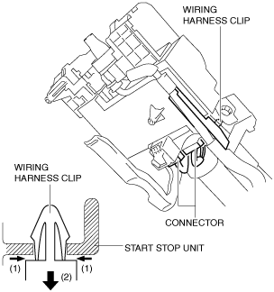
6.  While pressing the tabs of the clip in the direction of arrow (1) shown in the figure, press it in the direction of arrow (2) to detach the connector tabs from the start stop unit.

7.  Remove the wiring harness clip from the start stop unit.

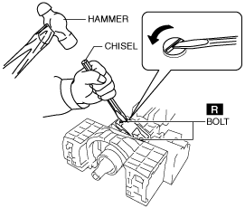
8.  Make a groove on the bolt head by punching it with a chisel using a hammer, and remove the bolts by rotating them counterclockwise.

am3uuw00009993

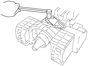
9.  Remove the bolts.

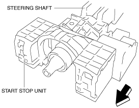
10.  Remove the start stop unit from the steering shaft by pulling it in the direction of the arrow shown in the figure.

am3uuw00009994

11.  Install in the reverse order of removal. (See Start Stop Unit Installation Note.)

12.  Perform the following when replacing the start stop unit.

•  Start stop unit configuration. (See START STOP UNIT CONFIGURATION (USING READ/WRITE FUNCTION).)
Note
•  If configuration cannot be performed by reading/writing of the vehicle specification information, perform the configuration using As-Built information after replacing the start stop unit. (See START STOP UNIT CONFIGURATION (USING AS-BUILT DATA).)
•  Immobilizer system-related parts programming. (See IMMOBILIZER SYSTEM-RELATED PARTS PROGRAMMING.)


Start Stop Unit Installation Note

1.  Temporarily install the start stop unit to the steering shaft using new start stop unit installation bolts.

2.  Tighten the start stop unit installation bolts until the heads break off.

ac5jjw00000877