|
1
|
DETERMINE IF MALFUNCTION CAUSE IS IMMOBILIZER SYSTEM OR OTHER
• Are any of the following conditions present?
-
― Engine does not start completely.
― PCM DTC P1260:00 is displayed.
|
Yes
|
Both conditions present:
• Go to Step 4.
|
|
No
|
Either or other condition present:
• Go to the next step.
|
|
2
|
INSPECT PUSH BUTTON START CONNECTOR CONNECTION
• Inspect the connection of the push button start connector.
• Is the push button start connector securely connected to the coil antenna?
|
Yes
|
Go to the next step.
|
|
No
|
Reconnect the push button start securely, then repeat from Step 1.
|
|
3
|
DETERMINE IF MALFUNCTION CAUSE IS INSTRUMENT CLUSTER OR OTHER
• Switch the ignition ON (engine off).
• Does the security indicator light flash?
|
Yes
|
Go to the next step.
|
|
No
|
Inspect the following wiring harness and connectors:
• Instrument cluster terminal B—Front body control module (FBCM) terminal 2K
• Instrument cluster terminal D—Front body control module (FBCM) terminal 2I
• Front body control module (FBCM) terminal 2P—PCM terminal 1BE
• Front body control module (FBCM) terminal 2N—PCM terminal 1AZ
-
― If there is any malfunction:
-
• Repair or replace the malfunctioning part according to the inspection results.
Inspect the instrument cluster.
• If there is any malfunction:
-
― Repair or replace the malfunctioning part according to the inspection results.
|
|
4
|
VERIFY IMMOBILIZER SYSTEM DTC
• Retrieve the immobilizer system DTC using the M-MDS.
• Are any DTCs present?
|
Yes
|
Go to the applicable DTC inspection.
|
|
No
|
Go to the next step.
|
|
5
|
VERIFY PCM DTC
• Retrieve any DTCs using the M-MDS.
• Are any continuous memory DTCs present?
|
Yes
|
Continuous memory DTC is displayed:
• Go to the applicable DTC inspection.
Communication error message is displayed:
• Inspect the following:
-
― Open circuit in wiring harness between main relay terminal E and PCM terminal 1AJ
― Open circuit in wiring harness between main relay terminal D and PCM terminal 1BI or 1BL
― Main relay (stuck open)
― Open or short circuit in wiring harness between DLC-2 and PCM terminal 1BE or 1AZ
― Open or poor ground circuit (PCM terminal 2D, 2BK, 2BL, 2BM and 2E)
― Poor connection of vehicle body ground
• Repair or replace the malfunctioning part according to the inspection results.
|
|
No
|
Go to the next step.
|
|
6
|
INSPECT POWER SUPPLY
• Access the VPWR PID using the M-MDS.
• Verify the VPWR PID value.
• Is the VPWR PID value B+?
|
Yes
|
Go to the next step.
|
|
No
|
Inspect the following:
• Battery connection
-
― If there is any malfunction:
-
• Repair or replace the malfunctioning part according to the inspection results, then repeat this step.
|
|
7
|
DETERMINE IF MALFUNCTION CAUSE IS STARTER RELAY CONTROL SIGNAL CIRCUIT OR OTHER
• Switch the ignition to START.
• Is a clicking sound heard from the starter relay?
|
Yes
|
Go to Step 18.
|
|
No
|
ATX:
• Go to Step 11.
MTX:
• Go to the next step.
|
|
8
|
DETERMINE IF MALFUNCTION CAUSE IS STARTER INTERLOCK SWITCH OR OTHER
• Switch the ignition off.
• Short the starter interlock switch terminals A and B (wiring harness-side) using a jumper wire.
• Switch the ignition to START.
• Does the engine start?
|
Yes
|
Inspect the starter interlock switch.
• If there is any malfunction:
-
― Replace the starter interlock switch, then repeat Step 7.
• If there is no malfunction:
-
― Go to the next step.
|
|
No
|
Go to the next step.
|
|
9
|
INSPECT STARTER INTERLOCK SWITCH CONNECTOR CONDITION
• Switch the ignition off.
• Disconnect the starter interlock switch connector.
• Inspect for poor connection (such as damaged/pulled-out pins, corrosion).
• Is there any malfunction?
|
Yes
|
Repair or replace the connector and/or terminals, then repeat Step 7.
|
|
No
|
Go to the next step.
|
|
10
|
INSPECT STARTER INTERLOCK SWITCH GROUND CIRCUIT FOR OPEN CIRCUIT
• Verify that the starter interlock switch connector is disconnected.
• Inspect for continuity between starter interlock switch terminal B (wiring harness-side) and body ground.
• Is there continuity?
|
Yes
|
Go to the next step.
|
|
No
|
Refer to the wiring diagram and verify whether or not there is a common connector between starter interlock switch terminal B and body ground.
If there is a common connector:
• Determine the malfunctioning part by inspecting the common connector and the terminal for corrosion, damage, or pin disconnection, and the common wiring harness for an open circuit.
• Repair or replace the malfunctioning part.
If there is no common connector:
• Inspect for the following:
-
― Open circuit between starter interlock switch and body ground
― Loose or lifting ground point
-
• Repair or replace the malfunctioning part.
Repeat Step 7.
|
|
11
|
INSPECT STARTER RELAY
• Switch the ignition off.
• Remove the starter relay.
• Inspect the starter relay.
• Is there any malfunction?
|
Yes
|
Replace the starter relay.
Repeat Step 7.
|
|
No
|
Go to the next step.
|
|
12
|
INSPECT START STOP UNIT CONNECTOR CONDITION
• Disconnect the start stop unit connector.
• Inspect for poor connection (such as damaged/pulled-out pins, corrosion).
• Is there any malfunction?
|
Yes
|
Repair or replace the connector and/or terminals, then repeat Step 7.
|
|
No
|
Go to the next step.
|
|
13
|
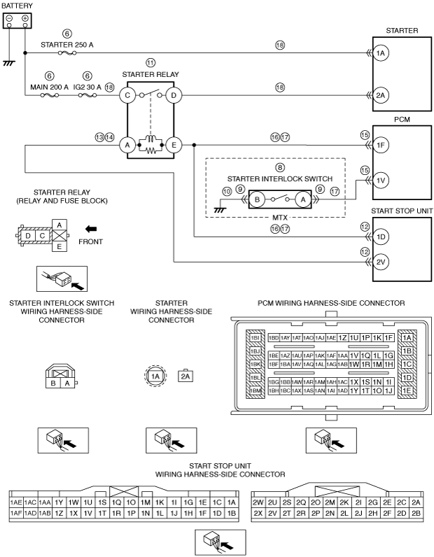
INSPECT STARTER RELAY CONTROL CIRCUIT FOR SHORT TO GROUND
• Starter relay is removed.
• Verify that the starter interlock switch connector is disconnected. (MTX)
• Verify that the start stop unit connector is disconnected.
• Inspect for continuity between starter relay terminal A (wiring harness-side) and body ground.
• Is there continuity?
|
Yes
|
Refer to the wiring diagram and verify whether or not there is a common connector between starter relay terminal A and start stop unit terminal 2V.
If there is a common connector:
• Determine the malfunctioning part by inspecting the common connector and the terminal for corrosion, damage, or pin disconnection, and the common wiring harness for a short to ground.
• Repair or replace the malfunctioning part.
If there is no common connector:
• Repair or replace the wiring harness which has a short to ground.
Repeat Step 7.
|
|
No
|
Go to the next step.
|
|
14
|
INSPECT STARTER RELAY CONTROL CIRCUIT FOR OPEN CIRCUIT
• Starter relay is removed.
• Verify that the starter interlock switch connector is disconnected. (MTX)
• Verify that the start stop unit connector is disconnected.
• Inspect for continuity between starter relay terminal A (wiring harness-side) and start stop unit terminal 2V (wiring harness-side).
• Is there continuity?
|
Yes
|
Go to the next step.
|
|
No
|
Refer to the wiring diagram and verify whether or not there is a common connector between starter relay terminal A and start stop unit terminal 2V.
If there is a common connector:
• Determine the malfunctioning part by inspecting the common connector and the terminal for corrosion, damage, or pin disconnection, and the common wiring harness for an open circuit.
• Repair or replace the malfunctioning part.
If there is no common connector:
• Repair or replace the wiring harness which has an open circuit.
Repeat Step 7.
|
|
15
|
INSPECT PCM CONNECTOR CONDITION
• Disconnect the PCM connector.
• Inspect for poor connection (such as damaged/pulled-out pins, corrosion).
• Is there any malfunction?
|
Yes
|
Repair or replace the connector and/or terminals, then repeat Step 7.
|
|
No
|
Go to the next step.
|
|
16
|
INSPECT STARTER RELAY CONTROL CIRCUIT FOR SHORT TO GROUND
• Starter relay is removed.
• Verify that the starter interlock switch connector is disconnected. (MTX)
• Verify that the start stop unit and PCM connectors are disconnected.
• Inspect for continuity between starter relay terminal E (wiring harness-side) and body ground.
• Is there continuity?
|
Yes
|
Refer to the wiring diagram and verify whether or not there is a common connector between the following terminals:
• Starter relay terminal E—PCM terminal 1F
• Starter relay terminal E—Start stop unit terminal 1D
If there is a common connector:
• Determine the malfunctioning part by inspecting the common connector and the terminal for corrosion, damage, or pin disconnection, and the common wiring harness for a short to ground.
• Repair or replace the malfunctioning part.
If there is no common connector:
• Repair or replace the wiring harness which has a short to ground.
Repeat Step 7.
|
|
No
|
Go to the next step.
|
|
17
|
INSPECT STARTER RELAY CONTROL CIRCUIT FOR OPEN CIRCUIT
• Starter relay is removed.
• Verify that the starter interlock switch connector is disconnected. (MTX)
• Verify that the start stop unit and PCM connectors are disconnected.
• Inspect for continuity between the following terminals (wiring harness-side):
-
― Starter relay terminal E—PCM terminal 1F
― Starter interlock switch terminal A—PCM terminal 1V (MTX)
― Starter relay terminal E—Start stop unit terminal 1D
• Is there continuity?
|
Yes
|
Inspect the start stop unit.
• If there is any malfunction:
-
― Replace the start stop unit, then repeat Step 7.
• If there is no malfunction:
-
― Go to the next step.
|
|
No
|
Refer to the wiring diagram and verify whether or not there is a common connector between the following terminals:
• Starter relay terminal E—PCM terminal 1F
• Starter interlock switch terminal A—PCM terminal 1V (MTX)
• Starter relay terminal E—Start stop unit terminal 1D
If there is a common connector:
• Determine the malfunctioning part by inspecting the common connector and the terminal for corrosion, damage, or pin disconnection, and the common wiring harness for an open circuit.
• Repair or replace the malfunctioning part.
If there is no common connector:
• Repair or replace the wiring harness which has an open circuit.
Repeat Step 7.
|
|
18
|
INSPECT WIRING HARNESS OF STARTER POWER SUPPLY CIRCUIT
• Inspect the following circuit:
-
― Between battery positive terminal and starter terminal 1A
― Between battery positive terminal and starter relay terminal C
― Between starter relay terminal D and starter terminal 2A
• Is there any malfunction?
|
Yes
|
Repair or replace the suspected wiring harness.
|
|
No
|
Go to the next step.
|
|
19
|
INSPECT STARTING SYSTEM
• Inspect the starting system.
• Is there any malfunction?
|
Yes
|
Repair or replace the malfunctioning part according to the inspection results.
|
|
No
|
Go to the next step.
|
|
20
|
INSPECT IMMOBILIZER SYSTEM RELATED CIRCUIT
• Inspect the following wiring harness and connectors:
-
― Between push button start terminal A and start stop unit terminal 1AC
― Between push button start terminal B and start stop unit terminal 1AE
― Between PCM terminal 1BE and start stop unit terminal 2M
― Between PCM terminal 1AZ and start stop unit terminal 2O
• Is there any malfunction?
|
Yes
|
Repair or replace the malfunctioning part according to the inspection results.
|
|
No
|
Go to the next step.
|
|
21
|
VERIFY PRESENT MALFUNCTION DTC
• Perform the KOEO self test.
• Are any DTCs present?
|
Yes
|
Go to the applicable DTC inspection.
|
|
No
|
Go to the next step.
|
|
22
|
DETERMINE IF MALFUNCTION CAUSE IS BASE ENGINE OR OTHER
• Inspect for a seized flywheel (MTX) or drive plate (ATX).
• Is the flywheel (MTX) or drive plate (ATX) seized?
|
Yes
|
Repair or replace the malfunctioning part according to the inspection results.
|
|
No
|
Base engine malfunction or engine damage during compression due to liquid (such as water, fuel, or engine oil) penetration into cylinder.
• Overhaul or replace the engine.
|
|
23
|
Verify the test results.
• If malfunction remains, inspect related Service information perform repair or diagnosis.
-
― If vehicle repaired, troubleshooting completed.
|