 |
am3zzw00016335
TIMING CHAIN REMOVAL/INSTALLATION [MZR 1.6]
id0110f6801000
1. Disconnect the negative battery cable. (See BATTERY REMOVAL/INSTALLATION [MZR 1.6].)
2. Remove the front wheel and tire (RH). (See GENERAL PROCEDURES (SUSPENSION).)
3. Remove the front under cover No.2 and splash shield. (See FRONT UNDER COVER No.2 REMOVAL/INSTALLATION.) (See SPLASH SHIELD REMOVAL/INSTALLATION.)
4. Drain the engine coolant. (See ENGINE COOLANT REPLACEMENT [MZR 1.6].)
5. Remove the ignition coils. (See IGNITION COIL REMOVAL/INSTALLATION [MZR 1.6].)
6. Set the wiring harness aside.
7. Set the cooler pipe and the cooler hose aside. (With A/C) (See REFRIGERANT LINE REMOVAL/INSTALLATION [MZR 1.6].)
8. Remove the drive belt. (See DRIVE BELT REMOVAL/INSTALLATION [MZR 1.6].)
9. Disconnect the crankshaft position (CKP) sensor connector.
10. Remove the generator. (See GENERATOR REMOVAL/INSTALLATION [MZR 1.6].)
11. Remove the water pump. (See WATER PUMP REMOVAL/INSTALLATION [MZR 1.6].)
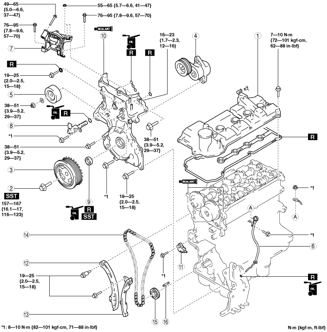
12. Remove in the order indicated in the table.
13. Install in the reverse order of removal.
14. Refill the engine coolant. (See ENGINE COOLANT REPLACEMENT [MZR 1.6].)
15. Start the engine, and inspect the following and adjust them if necessary.
am3zzw00016335
|
|
1
|
Cylinder head cover
|
|
2
|
Crankshaft pulley lock bolt
|
|
3
|
Crankshaft pulley
|
|
4
|
Drive belt auto tensioner
|
|
5
|
Idler
|
|
6
|
Dipstick pipe
|
|
7
|
No.3 engine mount
|
|
8
|
OCV
|
|
9
|
Front oil seal
|
|
10
|
Engine front cover
|
|
11
|
Chain tensioner
(See Chain Tensioner Removal Note.)
|
|
12
|
Chain tensioner arm
|
|
13
|
Chain guide
|
|
14
|
Timing chain
(See Timing Chain Removal Note.)
|
|
15
|
Crankshaft sprocket
|
|
16
|
Key
|
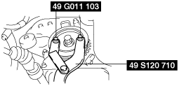
Crankshaft Pulley Lock Bolt Removal Note
1. Fix the crankshaft pulley using the SSTs, and remove the crankshaft pulley lock bolt.
am3zzw00006888
|
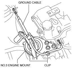
No.3 Engine Mount Removal Note
1. Remove the clips shown in the figure and set the ground cable aside.
am3zzw00014812
|
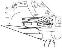
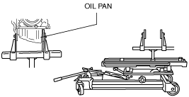
2. Support the engine using the following procedures.
am3zzw00006889
|
am3zzw00006890
|
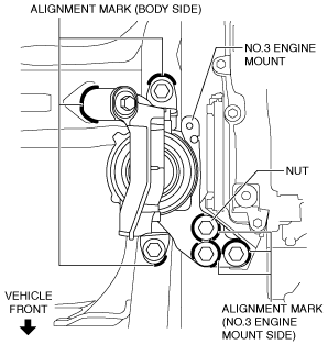
3. Place alignment marks on the locations shown in the figure so that they can be assembled to the same positions as before removal.
am3zzw00016102
|
4. Remove the No. 3 engine mount.
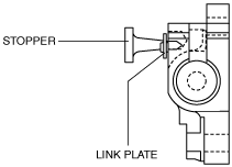
Chain Tensioner Removal Note
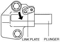
1. Push down the link plate of the timing chain tensioner using a thin flathead screwdriver (precision screwdriver), and release the plunger lock.
am3zzw00006891
|
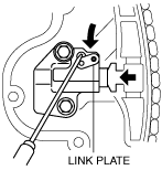
2. Push back the plunger slowly in the direction shown in the figure with the link plate still pushed down.
am3zzw00006892
|
3. Free the link plate with the plunger still pressed down.
4. Release the pressure slightly from the plunger, and move the plunger back and forth 2—3 mm{0.08—0.11 in}.
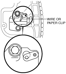
5. Insert an approx. 1.5 mm {0.06 in} wire or the paper clip where the link plate hole and the tensioner body hole overlap to fix the link plate and lock the plunger.
am3zzw00006893
|
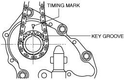
Timing Chain Removal Note
1. Rotate the crankshaft clockwise and align the key groove of the crankshaft sprocket to the timing mark, and then position the No.1 cylinder to TDC.
am3zzw00006894
|
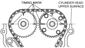
2. Align the timing marks on the camshaft sprockets so that they form a straight line in alignment with the upper horizontal surface of the cylinder head.
am2zzw00000113
|
3. Remove the timing chain.
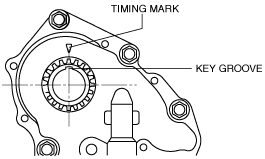
Timing Chain Installation Note
1. Align the key groove of the crankshaft sprocket to the timing mark, and then position the No.1 cylinder to TDC.
am3zzw00006895
|
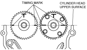
2. Align the timing marks on the camshaft sprockets so that they form a straight line in alignment with the upper horizontal surface of the cylinder head.
am2zzw00000115
|
3. Install the timing chain.
4. After installing the chain adjuster, remove the wire or the paper clip installed to the chain tensioner, and apply tension to the timing chain. (Remove the installed stopper when installing the new chain tensioner.)
am3zzw00006896
|
5. Verify that there is no slack on the timing chain, and then verify that each sprocket is positioned in the proper place again.
6. Rotate the crankshaft clockwise twice, and then inspect the valve timing.
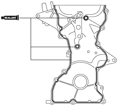
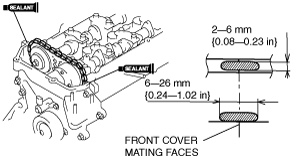
Engine Front Cover Installation Note
1. Apply the silicon sealant to the engine front cover as shown in the figure.
am2zzw00001758
|
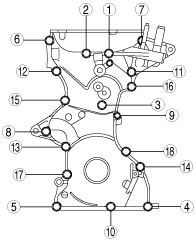
2. Tighten the engine front cover installation bolts in the order shown in the figure.
am2zzw00001759
|
|
Bolt number |
Tightening torque |
|---|---|
|
1—6, 8, 10,
12—15, 17, 18
|
19—25 N·m {2.0—2.5 kgf·m, 15—18 ft·lbf}
|
|
7, 11, 16
|
38—51 N·m {3.9—5.2 kgf·m, 29—37 ft·lbf}
|
|
9
|
8—10 N·m {82—101 kgf·cm, 71—88 in·lbf}
|
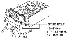
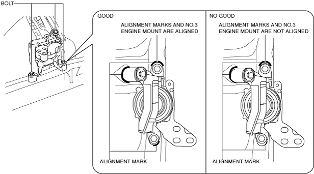
No.3 Engine Mount Installation Note
1. Tighten the stud bolts of the engine front cover.
am3zzw00006897
|
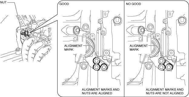
2. Temporarily tighten the No.3 engine mount installation bolts and nuts using the following procedure:
ac5uuw00003076
|
ac5uuw00003077
|
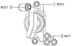
3. Tighten the No.3 engine mount installation bolts and nuts in the order shown in the figure.
ac5uuw00000675
|
Tightening torque
|
Installation position |
Tightening torque |
|---|---|
|
1
|
76—95 N·m {7.8—9.6 kgf·m, 57—70 ft·lbf}
|
|
2
|
55—65 N·m {5.7—6.6 kgf·m, 41—47 ft·lbf}
|
|
3
|
49—65 N·m {5.0—6.6 kgf·m, 37—47 ft·lbf}
|
4. Remove the engine lifter or garage jack.
5. Install the clips of the ground cable.
am3zzw00014812
|
Crankshaft Pulley Lock Bolt Installation Note
1. Fix the crankshaft pulley using the SSTs.
am3zzw00006888
|
2. Tighten the crankshaft pulley lock bolt.
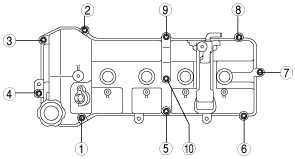
Cylinder Head Cover Installation Note
1. Apply silicon sealant as shown in the figure.
am2zzw00000122
|
2. Tighten the cylinder head cover installation bolts in the order shown in the figure.
am3zzw00006899
|