 |
am3zzw00016174
ENGINE MOUNT DISASSEMBLY/ASSEMBLY [MZR 1.6]
id0110f6806900
No.1 Engine Mount
1. Remove the front under cover No.2. (See FRONT UNDER COVER No.2 REMOVAL/INSTALLATION.)
2. Remove in the order indicated in the table.
3. Install in the reverse order of removal.
am3zzw00016174
|
|
1
|
No.1 engine mount rubber
|
|
2
|
Deadweight (ATX)
|
|
3
|
Bracket plate
|
|
4
|
No.1 engine mount bracket
|
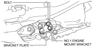
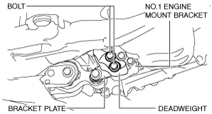
No.1 engine mount rubber removal note
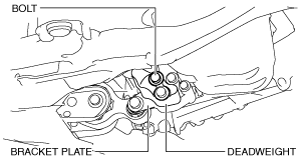
1. Loosen the bolts shown in the figure.
MTX
am3zzw00016175
|
ATX
am3zzw00016176
|
2. Remove the No.1 engine mount rubber.
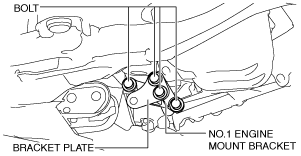
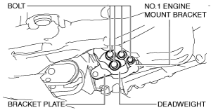
No.1 engine mount installation note
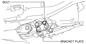
1. Install the following parts, and temporarily tighten the bolts shown in the figure.
am3zzw00016177
|
am3zzw00016178
|
2. Install the No.1 engine mount rubber and temporarily tighten the bolts shown in the figure.
am3zzw00016179
|
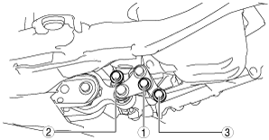
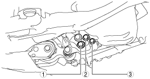
3. Tighten the No.1 engine mount bracket and bracket plate installation bolts in the order shown in the figure.
MTX
aaxjjw00018261
|
ATX
aaxjjw00018262
|
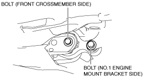
4. Tighten the bolt shown in the figure.
MTX
am3zzw00016180
|
ATX
am3zzw00016181
|
5. Tighten the No.1 engine mount rubber installation bolts shown in the figure.
am3zzw00016179
|
Tightening torque
|
Installation position |
Tightening torque |
|---|---|
|
No.1 engine mount bracket side
|
140—163 N·m {15—16 kgf·m, 104—120 ft·lbf}
|
|
Front crossmember side
|
130—164 N·m {14—16 kgf·m, 96—120 ft·lbf}
|
No.3 Engine Mount
1. Remove in the order indicated in the table.
2. Install in the reverse order of removal.
am3zzw00016182
|
|
1
|
No.3 engine mount
|
No.3 engine mount removal note
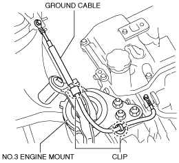
1. Remove the clips shown in the figure and set the ground cable aside.
am3zzw00016183
|
2. Remove the front under cover No.2. (See FRONT UNDER COVER No.2 REMOVAL/INSTALLATION.)
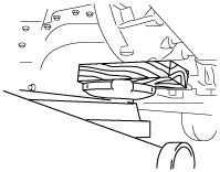
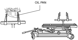
3. Support the engine using the following procedures.
am3zzw00006889
|
am3zzw00006890
|
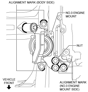
4. Place alignment marks on the locations shown in the figure so that they can be assembled to the same positions as before removal.
am3zzw00016184
|
5. Remove the No.3 engine mount.
No.3 engine mount installation note
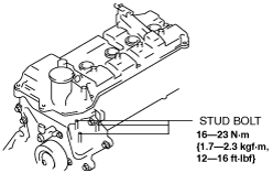
1. Tighten the stud bolts of the engine front cover.
am3zzw00006908
|
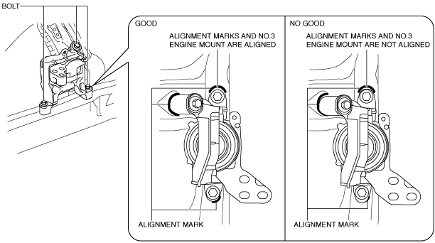
2. Temporarily tighten the No.3 engine mount installation bolts and nuts using the following procedure:
ac5uuw00003073
|
ac5uuw00003074
|
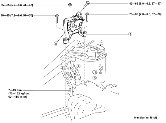
3. Tighten the No.3 engine mount installation bolts and nuts in the order shown in the figure.
am3zzw00016185
|
Tightening torque
|
Installation position |
Tightening torque |
|---|---|
|
1
|
76—95 N·m {7.8—9.6 kgf·m, 57—70 ft·lbf}
|
|
2
|
55—65 N·m {5.7—6.6 kgf·m, 41—47 ft·lbf}
|
|
3
|
49—65 N·m {5.0—6.6 kgf·m, 37—47 ft·lbf}
|
4. Remove the engine lifter or garage jack.
5. Install in the reverse order of removal.
No.4 Engine Mount
1. Disconnect the negative battery cable. (See NEGATIVE BATTERY CABLE DISCONNECTION/CONNECTION [MZR 1.6].)
2. Remove the air cleaner, air hose and fresh air duct as a single unit. (See INTAKE-AIR SYSTEM REMOVAL/INSTALLATION [MZR 1.6].)
3. Remove the battery tray and PCM component. (See BATTERY REMOVAL/INSTALLATION [MZR 1.6].)
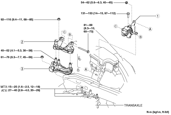
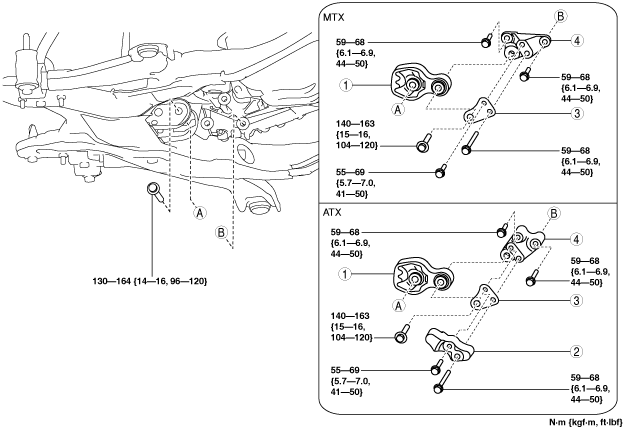
4. Remove in the order indicated in the table.
5. Install in the reverse order of removal.
am3zzw00016186
|
|
1
|
No.4 engine mount rubber
|
|
2
|
No.4 engine mount bracket
|
|
3
|
No.4 engine mount support bracket
|
No.4 engine mount rubber removal note
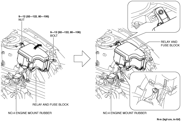
1. Remove the bolt and nut shown in the figure and set the relay and fuse block aside.
am3uuw00012267
|
2. Remove the front under cover No.2. (See FRONT UNDER COVER No.2 REMOVAL/INSTALLATION.)
3. Support the clutch housing (MTX) or the converter housing (ATX) using a jack with a wood slab of appropriate size inserted to secure the housing.
am3zzw00006889
|
4. Remove the No.4 engine mount rubber.
No.4 engine mount bracket removal note
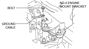
1. Remove the bolt shown in the figure and set the ground cable aside.
am3zzw00016187
|
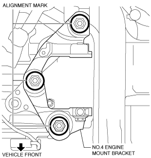
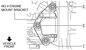
2. Place alignment marks on the locations shown in the figure so that they can be assembled to the same positions as before removal.
am3zzw00016188
|
3. Remove the No.4 engine mount bracket.
No.4 engine mount support bracket installation note
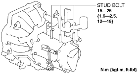
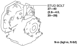
1. Tighten the stud bolts of the transaxle.
MTX
am3zzw00016189
|
ATX
am3zzw00016190
|
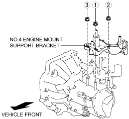
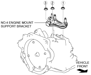
2. Tighten the No.4 engine mount support bracket installation nuts in the order shown in the figure.
MTX
am3zzw00016191
|
ATX
am3zzw00016192
|
No.4 engine mount bracket installation note
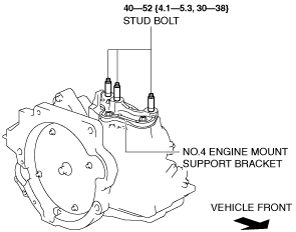
1. Tighten the stud bolts of the No.4 engine mount support bracket.
am3zzw00016193
|
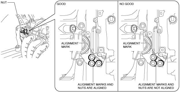
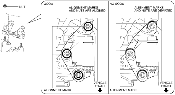
2. Align the alignment marks on the No.4 engine mount bracket and nuts, and temporarily tighten the nuts shown in the figure.
am3zzw00016194
|
3. Tighten the No.4 engine mount bracket installation nuts in the order shown in the figure.
am3zzw00016195
|
4. Install the ground cable to the No.4 engine mount bracket.
am3zzw00016187
|
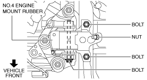
No.4 engine mount rubber installation note
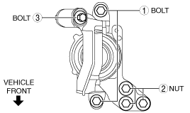
1. Install the No.4 engine mount rubber and temporarily tighten the nut and bolts shown in the figure.
am3zzw00016196
|
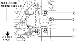
2. Tighten the No.4 engine mount rubber installation nut and bolts in the order shown in the figure.
am3zzw00016197
|
|
No. |
Tightening torque |
|---|---|
|
1, 2
|
131—153 N·m {14—15 kgf·m, 97—112 ft·lbf}
|
|
3
|
54—62 N·m {5.6—6.3 kgf·m, 40—45 ft·lbf}
|
|
4
|
81—99 N·m {8.3—10 kgf·m, 60—73 ft·lbf}
|
3. Remove the garage jack.
4. Install in the reverse order of removal.