 |
ac5wzw00008526
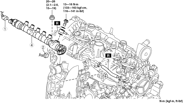
COMMON RAIL REMOVAL/INSTALLATION [SKYACTIV-D 2.2]
id0114z7803900
1. Disconnect the negative battery cable. (See NEGATIVE BATTERY CABLE DISCONNECTION/CONNECTION [SKYACTIV-D 2.2].)
2. Perform the “Fuel Line Safety Procedure” referring to the “BEFORE SERVICE PRECAUTION”. (See BEFORE SERVICE PRECAUTION [SKYACTIV-D 2.2].)
3. Remove the engine cover. (See ENGINE COVER REMOVAL/INSTALLATION [SKYACTIV-D 2.2].)
4. Remove the injection pipes (fuel injector side) and the injection pipe (supply pump side). (See INJECTION PIPE REMOVAL/INSTALLATION [SKYACTIV-D 2.2].)
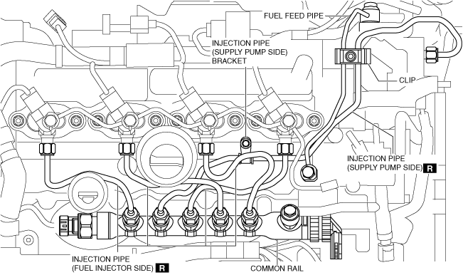
5. Remove in the order shown in the figure.
6. Install in the reverse order of removal.
7. Perform the “Fuel Hose Installation Procedure” and “Fuel Line Air Bleeding” referring to the “AFTER SERVICE PRECAUTION”. (See AFTER SERVICE PRECAUTION [SKYACTIV-D 2.2].)
ac5wzw00008526
|
|
1
|
Fuel pressure sensor connector
|
|
2
|
Fuel pressure relief valve connector
|
|
3
|
Fuel return hose No.4
|
|
4
|
Common rail
|
Common Rail Installation Note
1. Temporarily tighten the common rail.
am3zzw00021105
|
2. Temporarily tighten the new injection pipe (supply pump side).
3. Temporarily tighten the new injection pipes (fuel injector side).
4. Temporarily tighten the fuel return pipe (supply pump side).
5. Tighten the new clip. (See SUPPLY PUMP REMOVAL/INSTALLATION [SKYACTIV-D 2.2].)
6. Tighten the injection pipe (supply pump side) bracket.
7. Tighten the injection pipe (supply pump side) and the injection pipes (fuel injector side) on the common rail side.
8. Tighten the injection pipe (supply pump side) and the injection pipes (fuel injector side) on the fuel injector side.
9. Tighten the common rail.
10. Tighten the fuel return pipe (supply pump side).
Fuel Return Hose No.4 Installation Note
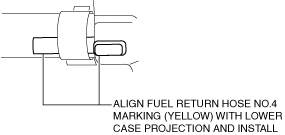
Lower case side
1. Install the fuel return hose No.4 as shown in the figure.
ac5wzw00008527
|
ac5wzw00008528
|
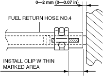
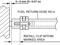
Common rail side
1. Install the fuel return hose No.4 as shown in the figure.
ac5wzw00008529
|