 |
am6zzw00011686
SUPPLY PUMP REMOVAL/INSTALLATION [SKYACTIV-D 2.2]
id0114z7805700
Operation After Replacing Supply Pump
1. If the supply pump is replaced, perform the following procedure.
|
STEP |
ACTION |
PAGE/CONDITION |
|---|---|---|
|
1
|
Perform supply pump data reset procedure.
|
|
|
2
|
Wait for 20 s.
|
—
|
|
3
|
Perform KOEO self-test procedure.
|
|
|
4
|
Maintain the idle status for 30 s with the following condition met.
• ECT: 60—100 °C {140—212 °F}
|
—
|
|
5
|
Perform KOER self-test procedure.
|
Supply Pump Removal/Installation
1. Disconnect the negative battery cable. (See NEGATIVE BATTERY CABLE DISCONNECTION/CONNECTION [SKYACTIV-D 2.2].)
2. Perform the “Fuel Line Safety Procedure” referring to the “BEFORE SERVICE PRECAUTION”. (See BEFORE SERVICE PRECAUTION [SKYACTIV-D 2.2].)
3. Remove the engine cover. (See ENGINE COVER REMOVAL/INSTALLATION [SKYACTIV-D 2.2].)
4. Remove the air cleaner. (See INTAKE-AIR SYSTEM REMOVAL/INSTALLATION [SKYACTIV-D 2.2].)
5. Remove the battery and the battery tray. (See BATTERY REMOVAL/INSTALLATION [SKYACTIV-D 2.2].)
6. Remove the following parts as a single unit: (See INTAKE-AIR SYSTEM REMOVAL/INSTALLATION [SKYACTIV-D 2.2].)
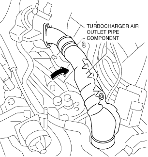
7. Set the turbocharger air outlet pipe component aside as a single unit as shown in the figure. (See INTAKE-AIR SYSTEM REMOVAL/INSTALLATION [SKYACTIV-D 2.2].)
am6zzw00011686
|
8. Drain the engine coolant. (See ENGINE COOLANT REPLACEMENT [SKYACTIV-D 2.2].)
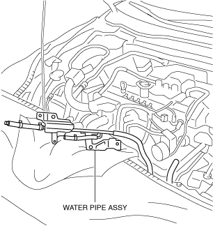
9. Set the water pipe assy aside as shown in the figure.
ac5wzw00005310
|
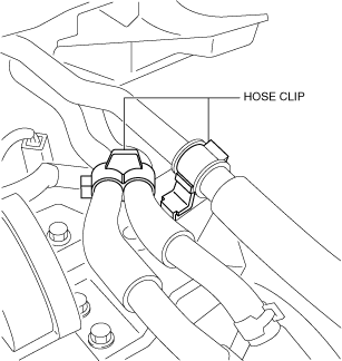
10. Detach the hose clip shown in the figure.
ac5wzw00004795
|
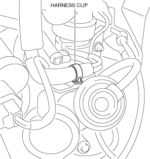
11. Detach the wiring harness clips shown in the figure.
ac5wzw00004796
|
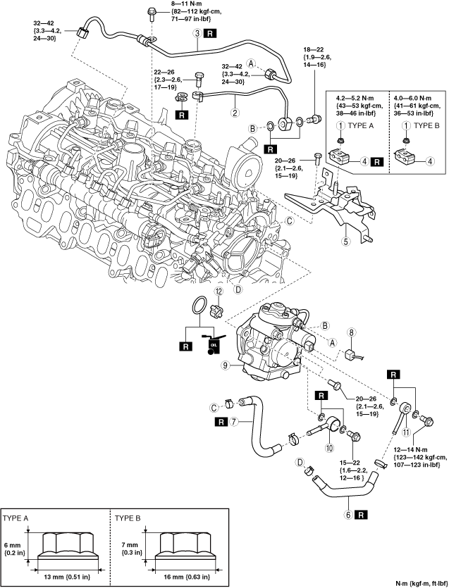
12. Remove in the order shown in the figure.
13. Install in the reverse order of removal.
14. Perform the fuel hose installation procedure and fuel line air bleeding referring to the “AFTER SERVICE PRECAUTION”. (See AFTER SERVICE PRECAUTION [SKYACTIV-D 2.2].)
am3zzw00016760
|
|
1
|
Clip installation nut
|
|
2
|
Fuel feed pipe
(See Fuel feed pipe removal note.)
|
|
3
|
Injection pipe (supply pump side)
|
|
4
|
Clip
|
|
5
|
Bracket
|
|
6
|
Fuel return hose
|
|
7
|
Fuel main hose
|
|
8
|
Suction control valve connector
|
|
9
|
Supply pump
(See Supply pump removal note.)
|
|
10
|
Connector No.1
|
|
11
|
Connector No.2
|
|
12
|
Spacer
|
Fuel feed pipe removal note
1. Set the harness protector connected to a bracket.
2. Remove the fuel feed pipe.
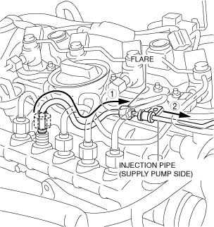
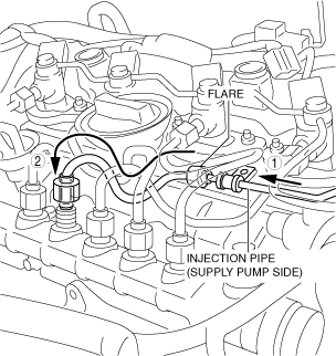
Injection pipe (supply pump side) removal note
1. Remove the injection pipe (supply pump side) as shown in the figure. (See INJECTION PIPE REMOVAL/INSTALLATION [SKYACTIV-D 2.2].)
ac5wzw00004798
|
2. Remove the injection pipe (supply pump side).
Supply pump removal note
1. Remove the supply pump and the suction control valve as a single unit.
2. Remove the suction control valve from a supply pump.
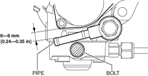
Connector No.1 installation note
1. Install the connector No.1 as shown in the figure so that the pipe does not cover the bolt.
ac5wzw00007124
|
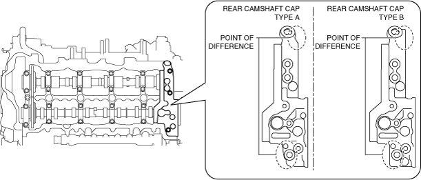
Supply pump installation note
1. I confirm the type of the rear camshaft cap with a difference to shown in the figure.
am3zzw00016761
|
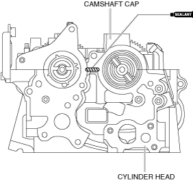
2. Apply silicone sealant to the areas shown in the figure.
am3zzw00016762
|
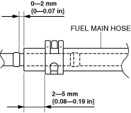
Fuel main hose installation note
1. Install fuel main hose as shown in the figure.
Supply pump side
am3zzw00016763
|
Lower case side
am3zzw00016763
|
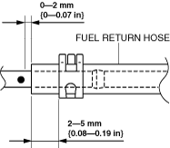
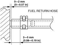
Fuel return hose installation note
1. Install fuel return hose as shown in the figure.
Supply pump side
am3zzw00016764
|
Lower case side
am3zzw00016765
|
Injection pipe (supply pump side) installation note
1. Install the injection pipe (supply pump side) as shown in the figure. (See INJECTION PIPE REMOVAL/INSTALLATION [SKYACTIV-D 2.2].)
am3zzw00016766
|
Fuel feed pipe installation note
1. Install the fuel feed pipe.
2. Connect the harness protector to a bracket.