 |
am3zzw00016733
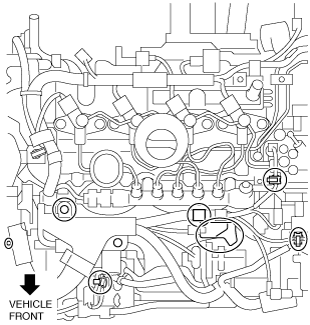
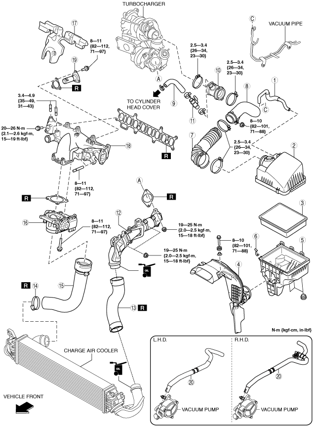
INTAKE-AIR SYSTEM REMOVAL/INSTALLATION [SKYACTIV-D 2.2]
id0113z7801900
1. Disconnect the negative battery cable. (See NEGATIVE BATTERY CABLE DISCONNECTION/CONNECTION [SKYACTIV-D 2.2].)
2. Remove in the order shown in the figure.
3. Install in the reverse order of removal.
am3zzw00016733
|
|
1
|
Vacuum hose
|
|
2
|
Air cleaner cover
|
|
3
|
Air cleaner element
|
|
4
|
Fresh-air duct
(See Fresh-air Duct Removal Note.)
|
|
5
|
Air cleaner case
|
|
6
|
Clip
|
|
7
|
Air hose
(See Air Hose Installation Note.)
|
|
8
|
Air inlet pipe
(See Air Inlet Pipe Removal Note.)
|
|
9
|
Breather hose
|
|
10
|
Turbocharger air inlet hose
|
|
11
|
Blow-by heater
|
|
12
|
Turbocharger air outlet pipe component
|
|
13
|
Charge air cooler inlet hose
|
|
14
|
Hose clamp
(See Hose Clamp Removal Note.)
(See Hose Clamp Installation Note.)
|
|
15
|
Charge air cooler outlet hose
|
|
16
|
Intake shutter valve
|
|
17
|
Intake manifold insulator
|
|
18
|
Intake manifold
(See Intake Manifold Removal Note.)
|
|
19
|
EGR pipe (Intake manifold side)
|
|
20
|
Vacuum hose
|
Air Cleaner Cover Removal Note
1. Remove the MAF sensor/IAT sensor No.1. (See MASS AIR FLOW (MAF) SENSOR/INTAKE AIR TEMPERATURE (IAT) SENSOR NO.1 REMOVAL/INSTALLATION [SKYACTIV-D 2.2].)
2. Remove the air cleaner cover.
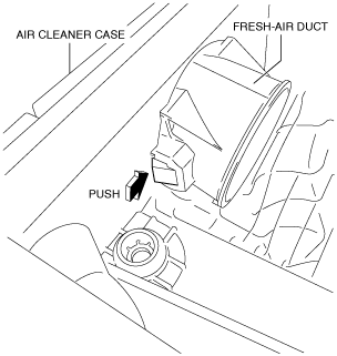
Fresh-air Duct Removal Note
1. Pull out the fresh-air duct from the air cleaner case while pressing the tab shown in the figure.
ac5wzw00004717
|
Air Inlet Pipe Removal Note
1. Remove the battery. (See BATTERY REMOVAL/INSTALLATION [SKYACTIV-D 2.2].)
2. Remove the air inlet pipe.
Turbocharger Air Outlet Pipe Component Removal Note
1. Remove the battery tray. (See BATTERY REMOVAL/INSTALLATION [SKYACTIV-D 2.2].)
2. Remove the turbocharger air outlet pipe component.
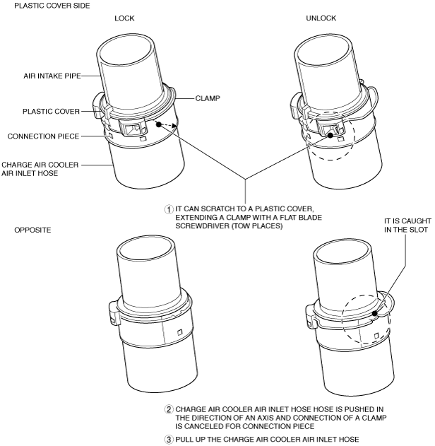
Charge Air Cooler Inlet Hose Removal Note
1. Release the lock and remove the charge air cooler inlet hose as shown in the figure.
am3zzw00016734
|
Hose Clamp Removal Note
1. Remove the front under cover No.1 and the front under cover No.2. (See FRONT UNDER COVER No.1 REMOVAL/INSTALLATION.) (See FRONT UNDER COVER No.2 REMOVAL/INSTALLATION.)
2. Remove the hose clamp.
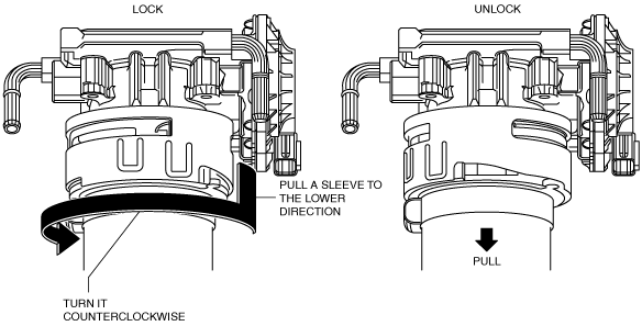
Charge Air Cooler Outlet Hose Removal Note
1. Release the lock of connector and remove the charge air cooler air outlet hose.
ac5wzw00005283
|
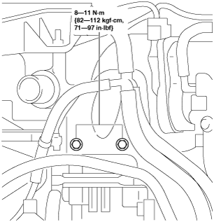
Intake Manifold Insulator Removal Note
1. Remove the bolts shown in the figure.
ac5wzw00004718
|
2. Remove the intake manifold insulator.
Intake Manifold Removal Note
1. Disconnect the connectors of the following parts:
2. Remove the wiring harness clips, bolts, nuts and harness bracket shown in the figure.
ac5wzw00005284
|
3. Disconnect the upper radiator hose from the intake manifold side.
4. Remove the EGR valve. (See EGR VALVE REMOVAL/INSTALLATION [SKYACTIV-D 2.2].)
5. Set the EGR cooler out of the way. (See EGR COOLER REMOVAL/INSTALLATION [SKYACTIV-D 2.2].)
6. Set the EGR cooler bypass valve out of the way. (See EGR COOLER BYPASS VALVE REMOVAL/INSTALLATION [SKYACTIV-D 2.2].)
7. Remove the intake manifold.
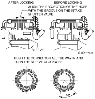
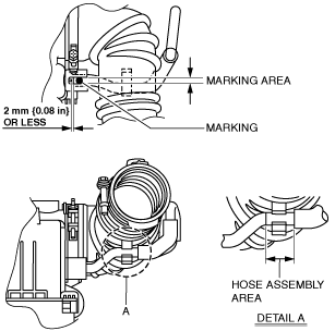
Charge Air Cooler Outlet Hose Installation Note
1. Install the charge air cooler outlet hose as shown in the figure.
am3zzw00016735
|
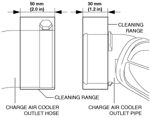
Hose Clamp Installation Note
1. Visually inspect the charge air cooler outlet hose and charge air cooler outlet pipe.
2. Use a clean cloth to clean the outer surfaces of the charge air cooler outlet pipe and the charge air cooler outlet hose.
am3zzw00016736
|
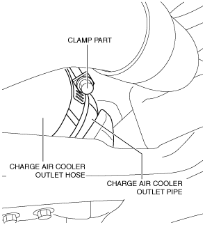
3. Temporarily install a new hose clamp to the charge air cooler outlet hose. (Do not tighten hose clamp)
am3zzw00016737
|
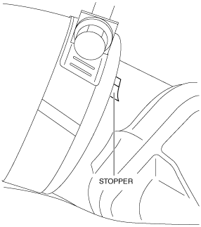
4. Insert the charge air cooler outlet hose until it contacts the charge air cooler outlet pipe stopper.
am3zzw00016738
|
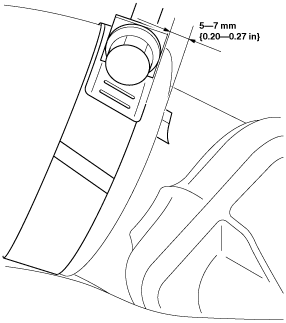
5. Re-position the temporarily installed hose clamp to the position 5—7 mm {0.20—0.27 in} from the charge air cooler outlet pipe stopper.
am3zzw00016739
|
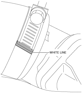
6. Tighten the hose clamp until the clamp end rides on top of the white line.
am3zzw00016740
|
7. Install the front under cover No.1 and the front under cover No.2. (See FRONT UNDER COVER No.1 REMOVAL/INSTALLATION.) (See FRONT UNDER COVER No.2 REMOVAL/INSTALLATION.)
Charge Air Cooler Inlet Hose Installation Note
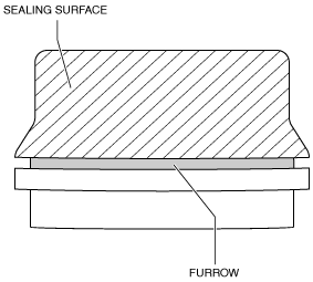
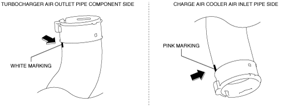
1. Clean the seal surface and furrow area of the turbocharger air outlet pipe component and charge air cooler air inlet pipe.
am3zzw00013791
|
2. Degrease the seal surface of the pipe, and verify if there is foreign matter penetration or scratches.
3. Apply engine oil to the seal surface of the pipe.
am3zzw00013792
|
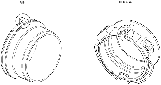
4. Align the pipe rib and connector groove positions, and install.
am3zzw00013793
|
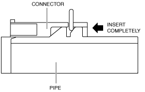
5. Insert the pipe connector completely into the connector.
am3zzw00013794
|
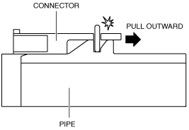
6. Pull the pipe outward and verify that a click sound is heard.
am3zzw00013795
|
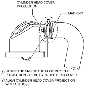
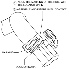
Breather Hose Installation Note
1. Install the breather hose as shown in the figure.
Cylinder head cover side
ac5wzw00005286
|
Blow-by heater side
ac5wzw00005287
|
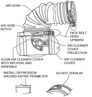
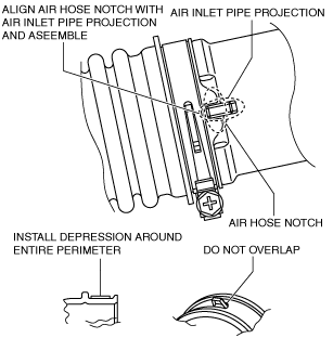
Air Hose Installation Note
1. Install the air hose as shown in the figure.
Air cleaner cover side
am3zzw00016741
|
Air inlet pipe side
am3zzw00016742
|
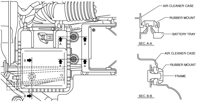
Air Cleaner Case Installation Note
1. Install the air cleaner case as shown in the figure.
ac5wzw00004724
|
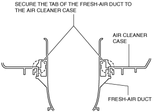
Fresh-air Duct Installation Note
1. Install the fresh-air duct as shown in the figure.
am3zzw00016743
|
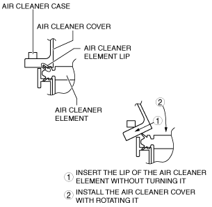
Air Cleaner Cover Installation Note
1. Install the air cleaner cover as shown in the figure.
am3zzw00016744
|
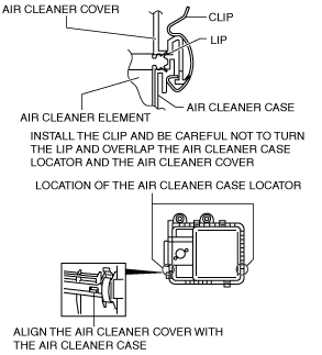
2. Secure the air cleaner cover and the air cleaner case with the clip.
am3zzw00016745
|
Vacuum Hose Installation Note
1. Install the vacuum hose as shown in the figure.
am3zzw00016746
|