 |
am3zzw00035102
EXHAUST SHUTTER VALVE INSPECTION [SKYACTIV-D 1.5]
id0116q2812200
PID/DATA Monitor Inspection
1. Connect the M-MDS to the DLC-2.
2. Switch the ignition ON (engine off).
3. Display PID EXHSHUT_ACT and simulation item EXHSHUT_DSD using the M-MDS. (See ON-BOARD DIAGNOSTIC TEST [SKYACTIV-D 1.5].)
4. Verify that the PID EXHSHUT_ACT value conforms to the simulation item EXHSHUT_DSD value when the exhaust shutter valve opening angle (simulation item: EXHSHUT_DSD) is changed using the simulation function.
Resistance Inspection
1. Switch the ignition OFF.
2. Disconnect the negative battery terminal. (See NEGATIVE BATTERY CABLE DISCONNECTION/CONNECTION [SKYACTIV-D 1.5].)
3. Disconnect the exhaust shutter valve connector. (See EXHAUST SHUTTER VALVE REMOVAL/INSTALLATION [SKYACTIV-D 1.5].)
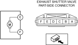
4. Inspect the resistance between exhaust shutter valve terminals E and F.
am3zzw00035102
|
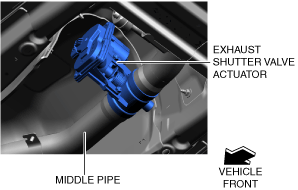
Visual Inspection
1. Connect the exhaust shutter valve connector. (See EXHAUST SHUTTER VALVE REMOVAL/INSTALLATION [SKYACTIV-D 1.5].)
2. Connect the negative battery terminal. (See NEGATIVE BATTERY CABLE DISCONNECTION/CONNECTION [SKYACTIV-D 1.5].)
3. Connect the M-MDS to the DLC-2.
4. Switch the ignition ON (engine off).
5. Display simulation item EXHSHUT_DSD using the M-MDS. (See ON-BOARD DIAGNOSTIC TEST [SKYACTIV-D 1.5].)
6. With the M-MDS connected to the DLC-2, move the vehicle to the position where the exhaust shutter valve motor can be verified as shown in the following figure.
am2zzw00016948
|
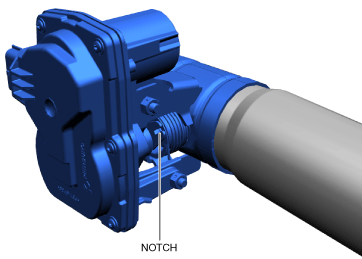
7. Verify that the notch of the exhaust shutter valve is driven as shown in the following figure when the exhaust shutter valve opening angle (simulation item: EXHSHUT_DSD) is changed using the simulation function.
ac30zw00004565
|