i-stop OFF SWITCH INSPECTION [SKYACTIV-G 1.5, SKYACTIV-G 2.0, SKYACTIV-G 2.5]


id0140g5888900

Note
•  The i-stop OFF switch is integrated with the cluster switch.
•  If the i-stop OFF switch is to be replaced, replace the cluster switch. (See CLUSTER SWITCH REMOVAL/INSTALLATION.)

Resistance Inspection

1.  Disconnect the negative battery cable. (See NEGATIVE BATTERY CABLE DISCONNECTION/CONNECTION [SKYACTIV-G 1.5, SKYACTIV-G 2.0, SKYACTIV-G 2.5].)

2.  Remove the following parts:

(1)  Driver's side front scuff plate (See FRONT SCUFF PLATE REMOVAL/INSTALLATION.)
(2)  Driver's side front side trim (See FRONT SIDE TRIM REMOVAL/INSTALLATION.)
(3)  Cluster switch (See CLUSTER SWITCH REMOVAL/INSTALLATION.)

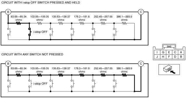
3.  Measure the resistance between cluster switch terminals B and C under the following conditions.

Resistance with i-stop OFF switch pressed and held
•  83.66—85.34 ohms
Resistance with any switch not pressed
•  1,139.99—1,163.01 ohms
am3zzw00014185
•  If not within the specification, replace the cluster switch. (See CLUSTER SWITCH REMOVAL/INSTALLATION.)


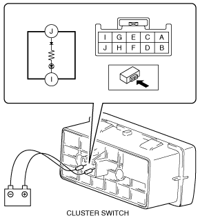
LED Illumination Inspection

1.  Disconnect the negative battery cable. (See NEGATIVE BATTERY CABLE DISCONNECTION/CONNECTION [SKYACTIV-G 1.5, SKYACTIV-G 2.0, SKYACTIV-G 2.5].)

2.  Remove the following parts:

(1)  Driver's side front scuff plate (See FRONT SCUFF PLATE REMOVAL/INSTALLATION.)
(2)  Driver's side front side trim (See FRONT SIDE TRIM REMOVAL/INSTALLATION.)
(3)  Cluster switch (See CLUSTER SWITCH REMOVAL/INSTALLATION.)

3.  Apply battery positive voltage to cluster switch terminal J, and connect terminal I to ground.

am3zzw00014186

4.  Verify that the LED is turned on.

•  If the LED does not turn on, replace the cluster switch. (See CLUSTER SWITCH REMOVAL/INSTALLATION.)