 |
am3zzw00014170
PCM INSPECTION [MZR 1.6]
id0140j7802500
Without Using the M-MDS
PCM terminal voltage table (Reference)
am3zzw00014170
|
|
Terminal |
Signal name |
Connected to |
Test condition |
Voltage (V) |
Inspection item |
|
|---|---|---|---|---|---|---|
|
1A
|
—
|
—
|
—
|
—
|
—
|
|
|
1B
|
—
|
—
|
—
|
—
|
—
|
|
|
1C
|
—
|
—
|
—
|
—
|
—
|
|
|
1D
|
—
|
—
|
—
|
—
|
—
|
|
|
1E
|
—
|
—
|
—
|
—
|
—
|
|
|
1F
|
Starter relay
|
Starter relay
|
Cranking
|
Below 1.0
|
• Starter relay
• Related wiring harness
|
|
|
1G
|
—
|
—
|
—
|
—
|
—
|
|
|
1H
|
—
|
—
|
—
|
—
|
—
|
|
|
1I
|
—
|
—
|
—
|
—
|
—
|
|
|
1J
|
Sensor GND
|
APP sensor No.2
|
Under any condition
|
Below 1.0
|
• Related wiring harness
|
|
|
1K
|
—
|
—
|
—
|
—
|
—
|
|
|
1L
|
—
|
—
|
—
|
—
|
—
|
|
|
1M
|
APP sensor No.1
|
APP sensor No.1
|
Switch ignition ON (engine off)
|
Accelerator pedal depressed
|
Approx. 3.4
|
• APP sensor No.1
• Related wiring harness
|
|
Accelerator pedal released
|
Approx. 0.4
|
|||||
|
1N
|
—
|
—
|
—
|
—
|
—
|
|
|
1O
|
Sensor GND
|
APP sensor No.1
|
Under any condition
|
Below 1.0
|
• Related wiring harness
|
|
|
1P
|
—
|
—
|
—
|
—
|
—
|
|
|
1Q
|
—
|
—
|
—
|
—
|
—
|
|
|
1R
|
MAF
|
MAF sensor
|
Switch ignition ON (engine off)
|
Approx. 0.7
|
• MAF sensor
• Related wiring harness
|
|
|
Idle
|
Approx. 1.3
|
|||||
|
1S
|
—
|
—
|
—
|
—
|
—
|
|
|
1T
|
GND
|
HO2S
|
Under any condition
|
Below 1.0
|
• Related wiring harness
|
|
|
1U
|
Brake switch (No.1 signal)
|
Brake switch (No.1 signal)
|
Brake pedal released
|
Below 1.0
|
• Brake switch (No.1 signal)
• Related wiring harness
|
|
|
Brake pedal fully depressed
|
B+
|
|||||
|
1V
|
Starter interlock*1
|
Starter interlock switch, start stop unit
|
Clutch pedal fully depressed
|
Below 1.0
|
• Starter interlock switch
• Start stop unit
• Related wiring harness
|
|
|
Clutch pedal released
|
B+
|
|||||
|
Selector lever position*2
|
TR switch, start stop unit
|
Selector lever position is not P or N position
|
B+
|
• TR switch
• Start stop unit
• Related wiring harness
|
||
|
Selector lever position is P or N position
|
Below 1.0
|
|||||
|
1W
|
IAT
|
IAT sensor
|
Switch ignition ON (engine off)
|
IAT is 20 °C {68 °F}
|
Approx. 2.2
|
• IAT sensor
• Related wiring harness
|
|
IAT is 30 °C {86 °F}
|
Approx. 1.8
|
|||||
|
1X
|
—
|
—
|
—
|
—
|
—
|
|
|
1Y
|
GND
|
MAF sensor
|
Under any condition
|
Below 1.0
|
• Related wiring harness
|
|
|
1Z
|
Cooling fan control
|
Cooling fan relay No.2, No.3
|
Cooling fan not operating
|
B+
|
• Cooling fan relay No.2, No.3
• Related wiring harness
|
|
|
Cooling fan operating
|
Below 1.0
|
|||||
|
1AA*1
|
CPP switch
|
CPP switch
|
Switch ignition ON (engine off)
|
Clutch pedal is depressed
|
Below 1.0
|
• CPP switch
• Related wiring harness
|
|
Clutch pedal is released
|
B+
|
|||||
|
1AB
|
HO2S
|
HO2S
|
Idle (after warm-up)
|
Alternates between 0 and 1.0
|
• HO2S
• Related wiring harness
|
|
|
1AC
|
—
|
—
|
—
|
—
|
—
|
|
|
1AD
|
GND
|
IAT sensor
|
Under any condition
|
Below 1.0
|
• Related wiring harness
|
|
|
1AE
|
Cooling fan control
|
Cooling fan relay No.1
|
Cooling fan not operating
|
B+
|
• Cooling fan relay No.1
• Related wiring harness
|
|
|
Cooling fan operating
|
Below 1.0
|
|||||
|
1AF
|
Brake switch (No.2 signal)
|
Brake switch (No.2 signal)
|
Brake pedal released
|
Below 1.0
|
• Brake switch (No.2 signal)
• Related wiring harness
|
|
|
Brake pedal fully depressed
|
B+
|
|||||
|
1AG
|
APP sensor No.2
|
APP sensor No.2
|
• APP sensor No.2
• Related wiring harness
|
|||
|
1AH
|
—
|
—
|
—
|
—
|
—
|
|
|
1AI
|
GND
|
Sensor shield
|
Under any condition
|
Below 1.0
|
• Related wiring harness
|
|
|
1AJ
|
Main relay
|
Main relay
|
Switch ignition off (engine off)
|
B+
|
• Main relay
• Related wiring harness
|
|
|
Switch ignition ON (engine off)
|
Below 1.0
|
|||||
|
1AK
|
Constant voltage (Vref)
|
APP sensor No.2
|
Under any condition
|
Approx. 5.0
|
• Related wiring harness
|
|
|
1AL
|
Ambient temperature
|
Ambient temperature sensor
|
Switch ignition ON (engine off)
|
AAT 20 °C {68 °F}
|
Below 1.0
|
• Ambient temperature sensor
• Related wiring harness
|
|
AAT 30 °C {104 °F}
|
B+
|
|||||
|
1AM
|
—
|
—
|
—
|
—
|
—
|
|
|
1AN
|
GND
|
Ambient temperature sensor
|
Under any condition
|
Below 1.0
|
• Related wiring harness
|
|
|
1AO
|
HO2S heater control
|
HO2S heater
|
Idle (after warm-up)
|
Below 1.0
|
• HO2S heater
• Related wiring harness
|
|
|
Heavy load
|
B+
|
|||||
|
1AP
|
Constant voltage (Vref)
|
APP sensor No.1
|
Under any condition
|
Approx. 5.0
|
• Related wiring harness
|
|
|
1AQ
|
—
|
—
|
—
|
—
|
—
|
|
|
1AR
|
Oil pressure
|
Oil pressure switch
|
Switch ignition ON (engine off)
|
Below 1.0
|
• Oil pressure switch
• Related wiring harness
|
|
|
1AS
|
GND
|
Refrigerant pressure sensor
|
Under any condition
|
Below 1.0
|
• Related wiring harness
|
|
|
1AT
|
A/C cut-off control
|
A/C relay
|
Idle, A/C operating
|
Below 1.0
|
• A/C relay
• Related wiring harness
|
|
|
Idle, A/C not operating
|
B+
|
|||||
|
1AU
|
Constant voltage (Vref)
|
Refrigerant pressure sensor
|
Switch ignition ON (engine off)
|
Approx. 5.0
|
• Related wiring harness
|
|
|
1AV
|
Refrigerant pressure
|
Refrigerant pressure sensor
|
Refrigerant pressure: 1.0 MPa {10 kgf/cm2, 145 psi}
|
Approx. 1.58
|
• Refrigerant pressure sensor
• Related wiring harness
|
|
|
Refrigerant pressure: 1.1 MPa {11 kgf/cm2, 160 psi}
|
Approx. 1.75
|
|||||
|
Refrigerant pressure: 1.2 MPa {12 kgf/cm2, 174 psi}
|
Approx. 1.88
|
|||||
|
1AW
|
—
|
—
|
—
|
—
|
—
|
|
|
1AX
|
—
|
—
|
—
|
—
|
—
|
|
|
1AY
|
Fuel pump control
|
Fuel pump relay
|
Switch ignition ON (engine off) and a certain period has elapsed
|
B+
|
• Fuel pump relay
• Related wiring harness
|
|
|
Cranking
|
Below 1.0
|
|||||
|
Idle
|
||||||
|
1AZ
|
CAN_L
|
CAN system related module, DLC-2
|
Because this terminal is for CAN, no valid determination of terminal voltage is possible.
|
• Related wiring harness
|
||
|
1BA
|
—
|
—
|
—
|
—
|
—
|
|
|
1BB
|
Power supply
|
HO2S heater
|
Switch ignition ON (engine off)
|
B+
|
• Related wiring harness
|
|
|
1BC
|
Power supply
|
MAF sensor
|
Idle
|
B+
|
• Related wiring harness
|
|
|
1BD
|
—
|
—
|
—
|
—
|
—
|
|
|
1BE
|
CAN_H
|
CAN system related module, DLC-2
|
Because this terminal is for CAN, no valid determination of terminal voltage is possible.
|
• Related wiring harness
|
||
|
1BF
|
—
|
—
|
—
|
—
|
—
|
|
|
1BG
|
—
|
—
|
—
|
—
|
—
|
|
|
1BH
|
—
|
—
|
—
|
—
|
—
|
|
|
1BI
|
Drive-by-wire control
|
Main relay
|
Switch ignition ON (engine off)
|
Drive-by-wire system is malfunction
|
Below 1.0
|
• Main relay
• Related wiring harness
|
|
Drive-by-wire system is normal
|
B+
|
|||||
|
1BJ
|
B+
|
Main relay
|
Ignition switch off
|
Below 1.0
|
• Main relay
• Related wiring harness
|
|
|
Switch ignition ON (engine off)
|
B+
|
|||||
|
1BK
|
B+
|
Main relay
|
Ignition switch off
|
Below 1.0
|
• Main relay
• Related wiring harness
|
|
|
Switch ignition ON (engine off)
|
B+
|
|||||
|
1BL
|
B+
|
Main relay
|
Ignition switch off
|
Below 1.0
|
• Main relay
• Related wiring harness
|
|
|
Switch ignition ON (engine off)
|
B+
|
|||||
|
1BM
|
Ignition (IG1)
|
IG1 relay
|
Switch ignition off
|
Below 1.0
|
• IG1 relay
• Related wiring harness
|
|
|
Switch ignition ON (engine off)
|
B+
|
|||||
|
2A*2
|
Shift solenoid B
|
(See PCM INSPECTION [FN4A-EL].)
|
||||
|
2B
|
Throttle control (+)
|
Throttle body (throttle valve actuator)
|
• Throttle valve actuator
• Related wiring harness
|
|||
|
2C
|
Power supply
|
A/F sensor heater
|
Switch ignition ON (engine off)
|
B+
|
• Related wiring harness
|
|
|
2D
|
GND
|
GND
|
Under any condition
|
Below 1.0
|
• Related wiring harness
|
|
|
2E
|
GND
|
GND
|
Under any condition
|
Below 1.0
|
• Related wiring harness
|
|
|
2F
|
Throttle control (–)
|
Throttle body (throttle valve actuator)
|
• Throttle valve actuator
• Related wiring harness
|
|||
|
2G
|
—
|
—
|
—
|
—
|
—
|
|
|
2H
|
Knocking
|
KS
|
Switch ignition ON (engine off). (Use digital type voltmeter, because measurement voltage will be detected less than true voltage when using analog type voltmeter.)
|
Approx. 2.4
|
• KS
• Related wiring harness
|
|
|
2I
|
Ignition coil power supply
|
Ignition coil
|
Switch ignition ON (engine off)
|
B+
|
• Ignition coil
• Related wiring harness
|
|
|
2J
|
Fuel injector No.3 power supply
|
Fuel injector No.3
|
Switch ignition ON (engine off)
|
B+
|
• Related wiring harness
|
|
|
2K
|
Fuel injection control
|
Fuel injector No.4
|
• Fuel injector No.4
• Related wiring harness
|
|||
|
2L
|
—
|
—
|
—
|
—
|
—
|
|
|
2M
|
Generator output voltage
|
Generator
|
• Generator
• Related wiring harness
|
|||
|
2N
|
Fuel injector No.4 power supply
|
Fuel injector No.4
|
Switch ignition ON (engine off)
|
B+
|
• Related wiring harness
|
|
|
2O
|
Power supply
|
CMP sensor, Purge solenoid valve, OCV, CKP sensor
|
Switch ignition ON (engine off)
|
B+
|
• Related wiring harness
|
|
|
2P
|
Fuel injection control
|
Fuel injector No.3
|
• Fuel injector No.3
• Related wiring harness
|
|||
|
2Q
|
ESA control
|
Ignition coil No.4
|
• Ignition coil No.4
• Related wiring harness
|
|||
|
2R
|
TP sensor No.2
|
TP sensor No.2
|
Switch ignition ON (engine off)
|
Accelerator pedal depressed
|
Approx. 0.5
|
• TP sensor No.2
• Related wiring harness
|
|
Accelerator pedal released
|
Approx. 3.9
|
|||||
|
2S
|
Fuel injector No.2 power supply
|
Fuel injector No.2
|
Switch ignition ON (engine off)
|
B+
|
• Related wiring harness
|
|
|
2T
|
Variable tumble control (-)
|
Variable tumble shutter valve actuator
|
The engine is cold.
|
Directly after switching ignition ON (engine off)
|
B+
|
• Variable tumble shutter valve actuator
• Related wiring harness
|
|
Except above
|
Below 1.0
|
|||||
|
2U
|
Fuel injection control
|
Fuel injector No.2
|
• Fuel injector No.2
• Related wiring harness
|
|||
|
2V
|
ESA control
|
Ignition coil No.3
|
• Ignition coil No.3
• Related wiring harness
|
|||
|
2X
|
Fuel injector No.1 power supply
|
Fuel injector No.1
|
Switch ignition ON (engine off)
|
B+
|
• Related wiring harness
|
|
|
2Y
|
Variable tumble control (+)
|
Variable tumble shutter valve actuator
|
The engine is hot.
|
Directly after switching ignition ON (engine off)
|
B+
|
• Variable tumble shutter valve actuator
• Related wiring harness
|
|
Idle after cold start
|
When the ECT is increased instant and reaches 60 °C {140 °F}
|
|||||
|
Except above
|
Below 1.0
|
|||||
|
2Z
|
Fuel injection control
|
Fuel injector No.1
|
• Fuel injector No.1
• Related wiring harness
|
|||
|
2AA
|
ESA control
|
Ignition coil No.2
|
• Ignition coil No.2
• Related wiring harness
|
|||
|
2AB*2
|
ATF temperature
|
(See PCM INSPECTION [FN4A-EL].)
|
||||
|
2AC
|
CMP
|
CMP sensor
|
• CMP sensor
• Related wiring harness
|
|||
|
2AD
|
GND
|
ECT sensor
|
Under any condition
|
Below 1.0
|
• Related wiring harness
|
|
|
2AE
|
Evaporative purge control
|
Purge solenoid valve
|
• Purge solenoid valve
• Related wiring harness
|
|||
|
2AF
|
ESA control
|
Ignition coil No.1
|
• Ignition coil No.1
• Related wiring harness
|
|||
|
2AG
|
ECT
|
ECT sensor
|
Switch ignition ON (engine off)
|
ECT is 20 °C {68 °F}
|
Approx. 3.0
|
• ECT sensor
• Related wiring harness
|
|
ECT is 80 °C {176 °F}
|
Approx. 0.9
|
|||||
|
2AH
|
CKP
|
CKP sensor
|
• CKP sensor
• Related wiring harness
|
|||
|
2AI
|
—
|
—
|
—
|
—
|
—
|
|
|
2AJ*2
|
Pressure control solenoid (+)
|
(See PCM INSPECTION [FN4A-EL].)
|
||||
|
2AK
|
—
|
—
|
—
|
—
|
—
|
|
|
2AL
|
TP sensor No.1
|
TP sensor No.1
|
Switch ignition ON (engine off)
|
Accelerator pedal depressed
|
Approx. 4.5
|
• TP sensor No.1
• Related wiring harness
|
|
Accelerator pedal released
|
Approx. 1.1
|
|||||
|
2AM
|
—
|
—
|
—
|
—
|
—
|
|
|
2AN*1
|
Back-up light
|
Back-up light switch
|
Shift lever is at R position
|
Below 1.0
|
• Back-up light switch
• Related wiring harness
|
|
|
Shift lever is not at R position
|
B+
|
|||||
|
2AO*2
|
Pressure control solenoid (–)
|
(See PCM INSPECTION [FN4A-EL].)
|
||||
|
2AP
|
Sensor GND
|
Throttle body (TP sensor)
|
Under any condition
|
Below 1.0
|
• Related wiring harness
|
|
|
2AQ
|
A/F sensor
|
A/F sensor
|
Idle (after warm-up)
|
Approx. 0
|
• A/F sensor
• Related wiring harness
|
|
|
2AR*2
|
Internal ground
|
Input/turbine speed sensor shield wire
|
Under any condition
|
Below 1.0
|
• Related wiring harness
|
|
|
2AS
|
Generator field coil control
|
Generator
|
• Generator
• Related wiring harness
|
|||
|
2AT*2
|
Shift solenoid D
|
(See PCM INSPECTION [FN4A-EL].)
|
||||
|
2AU
|
Constant voltage (Vref)
|
Throttle body (TP sensor)
|
Under any condition
|
Approx. 5.0
|
• Related wiring harness
|
|
|
2AV
|
A/F sensor
|
A/F sensor
|
Idle (after warm-up)
|
Approx. 2.4
|
• A/F sensor
• Related wiring harness
|
|
|
2AW
|
GND
|
CMP sensor, CKP sensor
|
Under any condition
|
Below 1.0
|
• Related wiring harness
|
|
|
2AX
|
GND
|
Sensor shield
|
Under any condition
|
Below 1.0
|
• Related wiring harness
|
|
|
2AY*2
|
Shift solenoid E
|
(See PCM INSPECTION [FN4A-EL].)
|
||||
|
2AZ
|
—
|
—
|
—
|
—
|
—
|
|
|
2BA*2
|
Input/turbine speed sensor (–)
|
(See PCM INSPECTION [FN4A-EL].)
|
||||
|
2BB*2
|
Sensor ground
|
(See PCM INSPECTION [FN4A-EL].)
|
||||
|
2BC
|
—
|
—
|
—
|
—
|
—
|
|
|
2BD
|
A/F sensor heater control
|
A/F sensor heater
|
• A/F sensor heater
• Related wiring harness
|
|||
|
2BE
|
Variable valve timing control
|
OCV
|
• OCV
• Related wiring harness
|
|||
|
2BF*2
|
Input/turbine speed sensor (+)
|
(See PCM INSPECTION [FN4A-EL].)
|
||||
|
2BG*2
|
Selector lever position
|
(See PCM INSPECTION [FN4A-EL].)
|
||||
|
2BH*1
|
Neutral switch
|
Neutral switch
|
Switch ignition ON (engine off)
|
Neutral
|
Below 1.0
|
• Neutral switch
• Related wiring harness
|
|
Except above
|
B+
|
|||||
|
2BI*2
|
Shift solenoid C
|
(See PCM INSPECTION [FN4A-EL].)
|
||||
|
2BJ*2
|
Shift solenoid A
|
(See PCM INSPECTION [FN4A-EL].)
|
||||
|
2BK
|
GND
|
GND
|
Under any condition
|
Below 1.0
|
• Related wiring harness
|
|
|
2BL
|
GND
|
GND
|
Under any condition
|
Below 1.0
|
• Related wiring harness
|
|
|
2BM
|
GND
|
GND
|
Under any condition
|
Below 1.0
|
• Related wiring harness
|
|
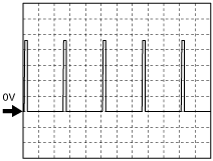
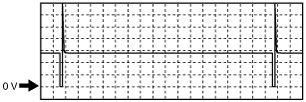
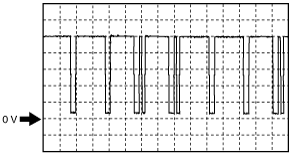
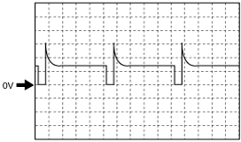
Inspection Using An Oscilloscope (Reference)
APP sensor (No.2) signal
Accelerator pedal released
aaxjjw00002881
|
Accelerator pedal depressed
aaxjjw00002882
|
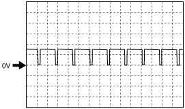
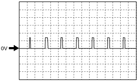
Fuel injection control signal
am2zzw00001204
|
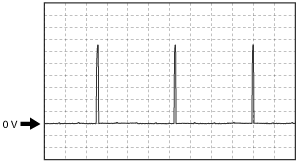
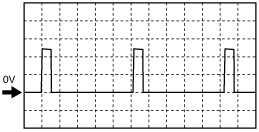
CMP signal
am2zzw00003587
|
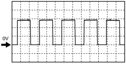
Evaporative purge control signal
am2zzw00003588
|
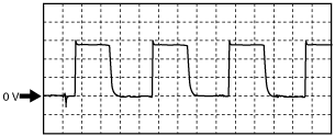
Variable valve timing control signal
am2zzw00003589
|
A/F sensor heater control signal
am2zzw00003590
|
CKP signal
am2zzw00003591
|
Generator output voltage signal
am2zzw00001210
|
Generator field coil control signal
am2zzw00001211
|
ESA control signal
am2zzw00001212
|
Throttle control (–) signal
adejjw00002871
|
Throttle control (+) signal
am2zzw00003592
|
Using The M-MDS
1. Connect the M-MDS to the DLC-2.
2. Switch the ignition ON (engine off).
3. Measure the PID value.
|
Item (definition) |
Unit/Condition |
Condition/Specification (Reference) |
Inspection item(s) |
PCM terminal |
|---|---|---|---|---|
|
AC_PRES
|
KPa {MPa}, mBar {Bar}, psi, in H20
|
• Displays refrigerant pressure
|
• Refrigerant pressure sensor
|
1AV
|
|
V
|
• Refrigerant pressure is 1.0 MPa {10 kgf/cm2, 145 psi}: Approx. 1.58 V
• Refrigerant pressure is 1.1 MPa {11 kgf/cm2, 160 psi}: Approx. 1.75 V
• Refrigerant pressure is 1.2 MPa {12 kgf/cm2, 174 psi}: Approx. 1.88 V
|
|||
|
AC_REQ
|
OFF/ON
|
• A/C switch OFF: OFF
• A/C switch ON: ON
|
• Perform applicable DTC trouble shooting
|
—
|
|
ACCS
|
OFF/ON
|
• A/C relay is OFF: OFF
• A/C relay is ON: ON
|
• A/C relay
• The following PIDs
|
1AT
|
|
AFR
|
—
|
• Target air fuel ratio is displayed
|
• A/F sensor
|
—
|
|
AFR_ACT
|
—
|
• Actual air fuel ratio is displayed
|
• A/F sensor
|
2AQ
2AV
|
|
ALTF
|
%
|
• Idle, E/L is operating: Duty value increases
|
• Generator
• The following PIDs
|
2AS
|
|
ALTT V
|
V
|
• Idle (no E/L): Approx. 14 V (This is an internal calculation value and differs from the terminal voltage.)
|
• Generator
|
2M
|
|
AMB_TEMP
|
°C, °F
|
• Displays ambient air temperature
|
• Ambient temperature sensor
|
1AL
|
|
APP*2
|
%
|
• Accelerator pedal released: Approx. 0 %
• Accelerator pedal depressed: Approx. 100 %
|
• The following PIDs
|
—
|
|
APP1
|
%
|
• Accelerator pedal released: Approx. 15 %
• Accelerator pedal depressed: Approx. 67 %
|
• APP sensor No.1
|
1M
|
|
V
|
• Accelerator pedal released: Approx. 0.4 V
• Accelerator pedal depressed: Approx. 3.4 V
|
|||
|
APP2
|
%
|
• Accelerator pedal released: Approx. 8 %
• Accelerator pedal depressed: Approx. 67 %
|
• APP sensor No.2
|
1AG
|
|
V
|
• Accelerator pedal released: Approx. 0.4 V
• Accelerator pedal depressed: Approx. 3.4 V
|
|||
|
ARPMDES
|
RPM
|
• Indicate target engine speed
|
• The following PIDs
|
—
|
|
BARO
|
KPa {MPa}, mBar {Bar}, psi, in H20
|
• Indicate BARO
|
• BARO sensor
|
—
|
|
V
|
• Switch ignition ON (engine off) (at sea level): approx. 4.1 V
|
|||
|
BOO
|
OFF/ON
|
• Brake pedal depressed: ON
• Brake pedal released: OFF
|
• Brake switch (No.1 signal)
|
1U
|
|
BPA
|
OFF/ON
|
• Brake pedal depressed: ON
• Brake pedal released: OFF
|
• Brake switch (No.2 signal)
|
1AF
|
|
CHRGLP
|
OFF/ON
|
• Charging system warning light not illuminated: Off
• Charging system warning light illuminated: On
|
• Perform applicable DTC troubleshooting
|
—
|
|
CPP*1
|
OFF/ON
|
• Clutch pedal depressed: On
• Clutch pedal released: Off
|
• CPP switch
|
1AA
|
|
CPP/PNP*1
|
OFF/ON
|
• Neutral: On
• Other than neutral: Off
|
• Neutral switch
|
2BH
|
|
DGP_DIS_1
|
km, ft, mi
|
• Displays traveled distance since the differential protection control operated due to excessive rotation difference between left/right drive wheels
|
—
|
—
|
|
DGP_DIS_2
|
km, ft, mi
|
• Displays traveled distance since DGP_MAX_DIF is updated
|
—
|
—
|
|
DGP_MAX_DIF
|
RPM
|
• Displays maximum rotation difference since the differential protection control operated due to excessive rotation difference between left/right drive wheels
|
—
|
—
|
|
DGP_SPD
|
KPH, MPH
|
• Displays vehicle speed with trailing wheels since the differential protection control operated due to excessive rotation difference between left/right drive wheels
|
—
|
—
|
|
DWN SW*2
|
||||
|
ECT
|
°C, °F
|
• Indicate ECT
|
• ECT sensor
|
2AG
|
|
V
|
• ECT is 20 °C {68 °F}: Approx. 3.0 V
• ECT is 80 °C {176 °F}: Approx. 0.9 V
|
|||
|
EQ_RAT11
|
—
|
• Idle after warm-up: Approx. 1
|
• A/F sensor
|
2AQ
2AV
|
|
EQ_RAT11_DSD
|
—
|
• Indicate the target lambda (Excess air factor = supplied air amount / theoretical air/fuel ratio)
|
• A/F sensor
|
—
|
|
ETC_ACT
|
°
|
• Indicate TP angle
|
• Throttle valve actuator
|
2B
2F
|
|
ETC_DSD
|
%
|
• Indicate target TP angle (percent)
|
• Throttle valve actuator
• The following PIDs
|
—
|
|
°
|
• Indicate target TP angle
|
|||
|
EVAPCP
|
%
|
• Switch ignition ON (engine off): 0 %
• Idle: 0 %
• Engine speed increase after warming up engine: Value increases
|
• Purge solenoid valve
• The following PIDs
|
2AE
|
|
FAN1
|
OFF/ON
|
• During test mode
CTP: Off
WOT: On
|
• Cooling fan relay No.1
• The following PIDs
|
1AE
|
|
FAN3
|
OFF/ON
|
• During test mode
CTP: Off
WOT: On
|
• Cooling fan relay No.2, No.3
• The following PIDs
|
1Z
|
|
FP
|
OFF/ON
|
• Switch ignition ON (engine off): OFF
• Cranking: ON
• Idle: ON
|
• Fuel pump relay
|
1AY
|
|
FUELPW
|
sec
|
• Idle: Approx. 1.8 ms
|
• Fuel injector
• The following PIDs
|
2K
2P
2U
2Z
|
|
FUELSYS
|
OL/CL/
OL_Drive/
OL_Fault/
CL_Fault
|
• Idle after warm-up: CL
|
• Fuel injector
• The following PIDs
|
—
|
|
GEAR*2
|
||||
|
HTM_CNT*2
|
||||
|
HTM_DIS*2
|
||||
|
HTR11
|
OFF/ON
|
• Idle (after warm up): ON↔OFF
|
• A/F sensor heater
• Inspect following PIDs
|
2BD
|
|
HTR12
|
OFF/ON
|
• Idle (after warm up): ONÛOFF
|
• HO2S heater control
• The following PIDs
|
1AO
|
|
%
|
• Ignition switched ON (engine off): 0 %
• Idle (after warm up): Approx. 40 %
|
|||
|
IAT
|
°C, °F
|
• Indicate IAT
|
• IAT sensor
|
1W
|
|
V
|
• IAT is 20 °C {68 °F}: Approx. 2.2 V
• IAT is 30 °C {86 °F}: Approx. 1.8 V
|
|||
|
IMRC
|
OFF/ON
|
• ECT below 60 °C {140 °F} and engine speed below 3,250 rpm: ON
• ECT above 60 °C {140 °F} while idling.: OFF
|
• Variable tumble shutter valve actuator
• The following PIDs
|
2T
2Y
|
|
%
|
• Indicate variable tumble shutter valve opening ratio
|
|||
|
INGEAR
|
OFF/ON
|
MTX
• When the following conditions are satisfied: ON
• Except above: OFF
ATX
• R, D, M position: ON
• Except above: OFF
|
MTX
• CPP switch
• Neutral switch
|
1AA
2BH
|
|
ATX
• TR switch
|
2BG
|
|||
|
ISC_FBK
|
%
|
ISC feedback value is displayed
|
• PCM
|
—
|
|
IVS
|
Idle/Off Idle
|
• Idle: Idle
• Racing: Off Idle
|
• Perform applicable DTC troubleshooting
|
—
|
|
KNOCKR
|
°
|
• Switch ignition ON (engine off): 0 °
• Idle: 0 °
|
• KS
|
2H
|
|
LINEDES*2
|
||||
|
LOAD
|
%
|
• Idle after warm-up: Approx. 20 %
|
• The following PIDs
|
—
|
|
LONGFT1
|
%
|
• Idle after warm-up: Approx.-15—15 %
|
• The following PIDs
|
—
|
|
LPS*2
|
||||
|
LOW_OIL
|
Never Detected/Detected
|
• Ignition switched ON (engine off): Detected
• Idle (after warm up): Detected
• Racing (engine speed is 2,000 rpm): Never Detected
|
• Oil pressure switch
|
1AR
|
|
MAF
|
g/sec
|
• Indicate MAF
|
• MAF sensor
|
1R
|
|
V
|
• Switch ignition ON (engine off): Approx. 0.7 V
• Idle (after warm up): Approx. 1.3 V
|
|||
|
MIL
|
OFF/ON
|
• Idle, check engine light illuminate: ON
• Idle, check engine light not illuminate: OFF
|
• Perform applicable DTC troubleshooting
|
—
|
|
MIL_DIS
|
km, ft, mi
|
• Indicate travelled distance since check engine light illuminated
|
• Perform applicable DTC troubleshooting
|
—
|
|
MNL SW*2
|
||||
|
O2S11
|
µA
|
• Idle (after warm up): Approx. 0 mA
|
• A/F sensor
|
2AQ
2AV
|
|
O2S12
|
V
|
• Idle (after warm up): 0—1.0 V
|
• HO2S
|
1AB
1T
|
|
OSS*2
|
||||
|
PCM_T
|
°C, °F
|
• Indicate PCM temperature
|
• PCM temperature sensor
|
—
|
|
PCM_T_Max
|
°C, °F
|
• Indicate maximum PCM temperature
|
• PCM
|
—
|
|
RO2FT1
|
%
|
• Idle (after warm up): Approx. 0
|
• Perform applicable DTC troubleshooting
|
—
|
|
RPM
|
RPM
|
• Indicate engine speed
|
• CKP sensor
|
2AH
|
|
SHRTFT1
|
%
|
• Idle (after warm up):-25—25 %
|
• Perform applicable DTC troubleshooting
|
—
|
|
SPARKADV
|
°
|
• Indicate ignition timing
|
• Ignition coil
• The following PIDs
|
2Q
2V
2AA
2AF
|
|
SSA/SS1*2
|
||||
|
SSB/SS2*2
|
||||
|
SSC/SS3*2
|
||||
|
SSD/SS4*2
|
||||
|
SSE_SS5*2
|
||||
|
Test
|
OFF/ON
|
• Test mode ON: ON
• Test mode OFF: OFF
|
—
|
—
|
|
TFT*2
|
||||
|
TFTV*2
|
||||
|
TP_REL
|
%
|
• Accelerator pedal released: Approx. 12 %
• Accelerator pedal depressed: Approx. 81 %
|
• The following PIDs
|
—
|
|
TP1
|
V
|
• Accelerator pedal released: Approx. 1.1 V
• Accelerator pedal depressed: Approx. 4.5 V
|
• TP sensor No.1
|
2AL
|
|
%
|
• Accelerator pedal released: Approx. 23%
• Accelerator pedal depressed: Approx. 91 %
|
|||
|
TP2
|
V
|
• Accelerator pedal released: Approx. 3.9 V
• Accelerator pedal depressed: Approx. 0.5 V
|
• TP sensor No.2
|
2R
|
|
%
|
• Accelerator pedal released: Approx. 22 %
• Accelerator pedal depressed: Approx. 91 %
|
|||
|
TPCT
|
V
|
• Switch ignition ON (engine off): Approx. 0.5 V
|
• TP sensor No.1, No.2
|
2R
2AL
|
|
TR_SENS*2
|
||||
|
TSS*2
|
||||
|
UP SW*2
|
||||
|
VPWR
|
V
|
• Displays battery voltage
|
• Battery
|
—
|
|
VSS
|
KPH, MPH
|
• Indicate vehicle speed
|
• DSC HU/CM
|
—
|
|
VT ACT1
|
°
|
• Idle: Approx. 0 °
• Racing (after warm up): 0—35 °
|
• CMP sensor
• CKP sensor
|
2AC
2AH
|
|
VT DIFF1
|
°
|
• Idle: approx. 0°
|
• CMP sensor
• The following PIDs
|
—
|
|
VT DUTY1
|
%
|
• Idle: Approx. 15 %
|
• OCV
• The following PIDs
|
2BE
|