 |
am3zzw00014639
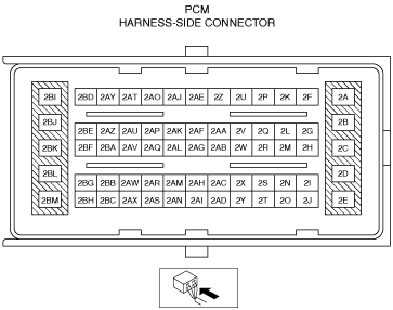
PCM INSPECTION [FN4A-EL]
id051701293500
1. Connect the voltmeter (-) lead to body GND.
2. Measure the voltage at each terminal.
PCM Terminal Voltage (Reference)
am3zzw00014639
|
|
Terminal |
Connected to |
Test Condition |
Voltage (V) |
Inspection Item |
|---|---|---|---|---|
|
2A
|
Shift solenoid B
|
(See Shift solenoid B.)
|
• Shift solenoid B
• Related harness
|
|
|
2AB
|
TFT sensor
|
ATF temperature 20 °C
|
Approx. 3.3
|
• TFT sensor
• Related harness
|
|
ATF temperature 65 °C
|
Approx. 1.3
|
|||
|
2AJ
|
Pressure control solenoid (+)
|
• Pressure control solenoid
• Related harness
|
||
|
2AO
|
Pressure control solenoid (-)
|
• Pressure control solenoid
• Related harness
|
||
|
2AR
|
Input/turbine speed sensor shield wire
|
Under any condition
|
Below 1.0
|
• Related harness
|
|
2AT
|
Shift solenoid D
|
D position 1GR
|
Below 1.0
|
• Shift solenoid D
• Related harness
|
|
D position 2GR
|
Below 1.0
|
|||
|
D position 3GR
|
Below 1.0
|
|||
|
D position 4GR
|
B+
|
|||
|
2AY
|
Shift solenoid E
|
TCC released
|
Below 1.0
|
• Shift solenoid E
• Related harness
|
|
TCC engaged
|
B+
|
|||
|
2BA
|
Input/turbine speed sensor (-)
|
(See Input/turbine speed sensor.)
|
• Input/turbine speed sensor
• Related harness
|
|
|
2BB
|
TR switch, TFT sensor
|
Under any condition
|
Below 1.0
|
• Related harness
|
|
2BF
|
Input/turbine speed sensor (+)
|
(See Input/turbine speed sensor.)
|
• Input/turbine speed sensor
• Related harness
|
|
|
2BG
|
TR switch
|
P position
|
4.3—4.8
|
• TR switch
• Related harness
|
|
R position
|
3.8—4.2
|
|||
|
N position
|
3.0—3.5
|
|||
|
D position
|
2.2—2.7
|
|||
|
M position
|
2.2—2.7
|
|||
|
2BI
|
Shift solenoid C
|
(See Shift solenoid C.)
|
• Shift solenoid C
• Related harness
|
|
|
2BJ
|
Shift solenoid A
|
(See Shift solenoid A.)
|
• Shift solenoid A
• Related harness
|
|
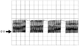
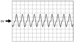
Input/Output Wave From (Reference)
Shift solenoid A
aaxjjw00001010
|
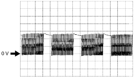
Shift solenoid B
aaxjjw00001011
|
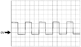
Shift solenoid C
aaxjjw00001012
|
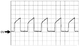
Pressure control solenoid (+)
aaxjjw00001014
|
Pressure control solenoid (-)
aaxjjw00001015
|
Input/turbine speed sensor
ampjjw00005641
|