DTC C0031:11/C0031:15/C0034:11/C0034:15/C0037:11/C0037:15/C003A:11/C003A:15 [ANTILOCK BRAKE SYSTEM (ABS)]


id0402b0180700

DTC
C0031:11, C0031:15
LF ABS wheel-speed sensor
C0034:11, C0034:15
RF ABS wheel-speed sensor
C0037:11, C0037:15
LR ABS wheel-speed sensor
C003A:11, C003A:15
RR ABS wheel-speed sensor
DETECTION CONDITION
•  C0031:11, C0034:11, C0037:11, C003A:11
―  Short to ground has been detected in the ABS wheel-speed sensor wiring harness on any of the four vehicle wheels.
•  C0031:15, C0034:15, C0037:15, C003A:15
―  Open circuit or short to power supply has been detected in the ABS wheel-speed sensor wiring harness on any of the four vehicle wheels.
FAIL-SAFE FUNCTION
•  Illuminates the ABS warning light.
•  Inhibits the ABS control.
(Additionally, when any malfunction is detected in two wheels or more, EBD control is inhibited and the brake system warning light is illuminated.)
POSSIBLE CAUSE
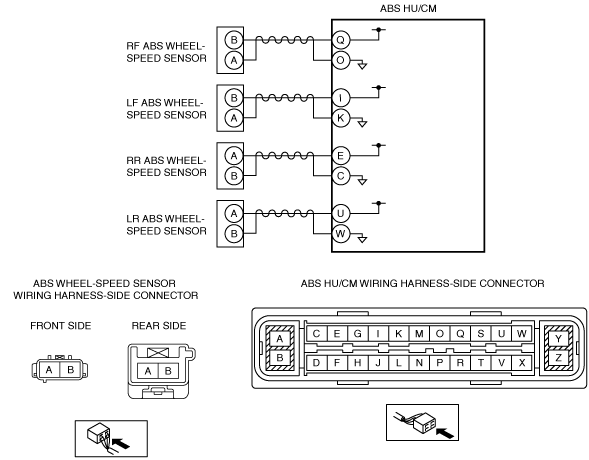
•  Open circuit or short to ground/power supply in the wiring harness between the following ABS HU/CM terminals and ABS wheel-speed sensor terminals:
―  ABS HU/CM terminal Q—RF ABS wheel-speed sensor terminal B
―  ABS HU/CM terminal O—RF ABS wheel-speed sensor terminal A
―  ABS HU/CM terminal I—LF ABS wheel-speed sensor terminal B
―  ABS HU/CM terminal K—LF ABS wheel-speed sensor terminal A
―  ABS HU/CM terminal E—RR ABS wheel-speed sensor terminal A
―  ABS HU/CM terminal C—RR ABS wheel-speed sensor terminal B
―  ABS HU/CM terminal U—LR ABS wheel-speed sensor terminal A
―  ABS HU/CM terminal W—LR ABS wheel-speed sensor terminal B
•  Malfunction in the ABS wheel-speed sensor
•  Poor connection at connectors (female terminal)
•  ABS HU/CM malfunction

Diagnostic procedure

STEP

INSPECTION

ACTION

1
INSPECT ABS WHEEL-SPEED SENSOR FOR SHORT TO GROUND
•  Switch the ignition to off.
•  Disconnect the ABS HU/CM connectors.
•  Inspect for continuity between the following ABS HU/CM connector terminals (vehicle harness-side) and body ground:
―  RF ABS wheel-speed sensor (+): Q
―  RF ABS wheel-speed sensor (-): O
―  LF ABS wheel-speed sensor (+): I
―  LF ABS wheel-speed sensor (-): K
―  RR ABS wheel-speed sensor (+): E
―  RR ABS wheel-speed sensor (-): C
―  LR ABS wheel-speed sensor (+): U
―  LR ABS wheel-speed sensor (-): W
•  Is there continuity?
Yes
Go to the next step.
No
Go to Step 3.
2
INSPECT ABS WHEEL-SPEED SENSOR WIRING HARNESS FOR SHORT TO GROUND
•  Disconnect the ABS wheel-speed sensor connectors.
•  Inspect for continuity between the following ABS HU/CM connector terminals (vehicle harness-side) and body ground:
―  RF ABS wheel-speed sensor (+): Q
―  RF ABS wheel-speed sensor (-): O
―  LF ABS wheel-speed sensor (+): I
―  LF ABS wheel-speed sensor (-): K
―  RR ABS wheel-speed sensor (+): E
―  RR ABS wheel-speed sensor (-): C
―  LR ABS wheel-speed sensor (+): U
―  LR ABS wheel-speed sensor (-): W
•  Is there continuity?
Yes
Refer to the wiring diagram and verify whether or not there is a common connector between the ABS HU/CM connector terminals (vehicle harness-side) and the following vehicle harness-side connector terminals of the ABS wheel-speed sensors:
•  RF ABS wheel-speed sensor (+): Q—B
•  RF ABS wheel-speed sensor (-): O—A
•  LF ABS wheel-speed sensor (+): I—B
•  LF ABS wheel-speed sensor (-): K—A
•  RR ABS wheel-speed sensor (+): E—A
•  RR ABS wheel-speed sensor (-): C—B
•  LR ABS wheel-speed sensor (+): U—A
•  LR ABS wheel-speed sensor (-): W—B
If there is a common connector:
•  Determine the malfunctioning part by inspecting the common connector and the terminal for corrosion, damage, or pin disconnection, and the common wiring harness for a short to ground.
•  Repair or replace the malfunctioning part.
If there is no common connector:
•  Repair or replace the wiring harness which has a short to ground.
Go to Step 5.
No
Replace the ABS wheel-speed sensor, then go to Step 5.
3
INSPECT FOR OPEN CIRCUIT IN ABS WHEEL-SPEED SENSOR WIRING HARNESS
•  Inspect for continuity between the ABS HU/CM connectors (vehicle harness-side) and the following vehicle harness-side connector terminals of the ABS wheel-speed sensors:
―  RF ABS wheel-speed sensor (+): Q—B
―  RF ABS wheel-speed sensor (-): O—A
―  LF ABS wheel-speed sensor (+): I—B
―  LF ABS wheel-speed sensor (-): K—A
―  RR ABS wheel-speed sensor (+): E—A
―  RR ABS wheel-speed sensor (-): C—B
―  LR ABS wheel-speed sensor (+): U—A
―  LR ABS wheel-speed sensor (-): W—B
•  Is there continuity?
Yes
Go to the next step.
No
Refer to the wiring diagram and verify whether or not there is a common connector between the ABS HU/CM connector terminals (vehicle harness-side) and the following vehicle harness-side connector terminals of the ABS wheel-speed sensors:
•  RF ABS wheel-speed sensor (+): Q—B
•  RF ABS wheel-speed sensor (-): O—A
•  LF ABS wheel-speed sensor (+): I—B
•  LF ABS wheel-speed sensor (-): K—A
•  RR ABS wheel-speed sensor (+): E—A
•  RR ABS wheel-speed sensor (-): C—B
•  LR ABS wheel-speed sensor (+): U—A
•  LR ABS wheel-speed sensor (-): W—B
If there is a common connector:
•  Determine the malfunctioning part by inspecting the common connector and the terminal for corrosion, damage, or pin disconnection, and the common wiring harness for an open circuit.
•  Repair or replace the malfunctioning part.
If there is no common connector:
•  Repair or replace the wiring harness which has an open circuit.
Go to the Step 5.
4
INSPECT ABS WHEEL-SPEED SENSOR WIRING HARNESS FOR SHORT TO POWER SUPPLY
•  Inspect for voltage between the following ABS HU/CM connector terminals (vehicle harness-side) and body ground:
―  RF ABS wheel-speed sensor (+): Q
―  RF ABS wheel-speed sensor (-): O
―  LF ABS wheel-speed sensor (+): I
―  LF ABS wheel-speed sensor (-): K
―  RR ABS wheel-speed sensor (+): E
―  RR ABS wheel-speed sensor (-): C
―  LR ABS wheel-speed sensor (+): U
―  LR ABS wheel-speed sensor (-): W
•  Is the voltage 1 V or less?
Yes
Go to the next step.
No
Refer to the wiring diagram and verify whether or not there is a common connector between the ABS HU/CM connector terminals (vehicle harness-side) and the following vehicle harness-side connector terminals of the ABS wheel-speed sensors:
•  RF ABS wheel-speed sensor (+): Q—B
•  RF ABS wheel-speed sensor (-): O—A
•  LF ABS wheel-speed sensor (+): I—B
•  LF ABS wheel-speed sensor (-): K—A
•  RR ABS wheel-speed sensor (+): E—A
•  RR ABS wheel-speed sensor (-): C—B
•  LR ABS wheel-speed sensor (+): U—A
•  LR ABS wheel-speed sensor (-): W—B
If there is a common connector:
•  Determine the malfunctioning part by inspecting the common connector and the terminal for corrosion, damage, or pin disconnection, and the common wiring harness for a short to power supply.
•  Repair or replace the malfunctioning part.
If there is no common connector:
•  Repair or replace the wiring harness which has a short to power supply.
Go to the next step.
5
VERIFY THAT THE SAME DTC IS NOT PRESENT
•  Reconnect all disconnected connectors.
•  Clear the DTCs from the memory.
•  Are the same DTCs present?
Yes
Repeat the inspection from Step 1.
If the malfunction recurs, replace the ABS HU/CM, then go to the next step.
No
Go to the next step.
6
VERIFY THAT NO OTHER DTCS ARE PRESENT
•  Are any other DTCs output?
Yes
Go to the applicable DTC inspection.
No
DTC troubleshooting completed.