DTC C0031:11/C0031:15/C0034:11/C0034:15/C0037:11/C0037:15/C003A:11/C003A:15 [DYNAMIC STABILITY CONTROL (DSC)]


id0402b2180700

DTC
C0031:11, C0031:15
LF ABS wheel-speed sensor
C0034:11, C0034:15
RF ABS wheel-speed sensor
C0037:11, C0037:15
LR ABS wheel-speed sensor
C003A:11, C003A:15
RR ABS wheel-speed sensor
DETECTION CONDITION
•  C0031:11, C0034:11, C0037:11, C003A:11
―  Short to ground has been detected in the ABS wheel-speed sensor wiring harness on any of the four vehicle wheels.
•  C0031:15, C0034:15, C0037:15, C003A:15
―  Open circuit or short to power supply has been detected in the ABS wheel-speed sensor wiring harness on any of the four vehicle wheels.
FAIL-SAFE FUNCTION
•  Illuminates the ABS warning light, TCS/DSC indicator light, Mazda Radar Cruise Control (MRCC) warning light*1, and Smart Brake Support/Smart City Brake Support (SBS/SCBS) indicator light (amber)*1.
•  Tire pressure monitoring system warning light*1 illuminates after flashes.
•  Inhibits the ABS, TCS, DSC, brake assist control, vehicle roll prevention function*1, Hill Launch Assist (HLA), TPMS*1, Secondary Collision Reduction (SCR)*1, Mazda Radar Cruise Control (MRCC)*1, Smart Brake Support (SBS)*1, and Smart City Brake Support (SCBS)*1 controls.
(Additionally, when any malfunction is detected in two wheels or more, EBD control is inhibited and the brake system warning light is illuminated.)
*1: If equipped.
POSSIBLE CAUSE
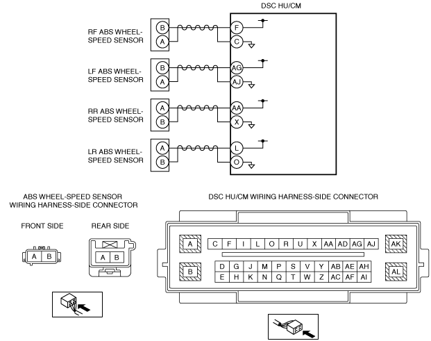
•  Open circuit or short to ground/power supply in the wiring harness between the following DSC HU/CM terminals and ABS wheel-speed sensor terminals:
―  DSC HU/CM terminal F—RF ABS wheel-speed sensor terminal B
―  DSC HU/CM terminal C—RF ABS wheel-speed sensor terminal A
―  DSC HU/CM terminal AG—LF ABS wheel-speed sensor terminal B
―  DSC HU/CM terminal AJ—LF ABS wheel-speed sensor terminal A
―  DSC HU/CM terminal AA—RR ABS wheel-speed sensor terminal A
―  DSC HU/CM terminal X—RR ABS wheel-speed sensor terminal B
―  DSC HU/CM terminal L—LR ABS wheel-speed sensor terminal A
―  DSC HU/CM terminal O—LR ABS wheel-speed sensor terminal B
•  Malfunction in the ABS wheel-speed sensor
•  Poor connection at connectors (female terminal)
•  DSC HU/CM malfunction

Diagnostic procedure

STEP

INSPECTION

ACTION

1
INSPECT ABS WHEEL-SPEED SENSOR FOR SHORT TO GROUND
•  Switch the ignition to off.
•  Disconnect the DSC HU/CM connectors.
•  Inspect for continuity between the following DSC HU/CM connector terminals (vehicle harness-side) and body ground:
―  RF ABS wheel-speed sensor (+): F
―  RF ABS wheel-speed sensor (-): C
―  LF ABS wheel-speed sensor (+): AG
―  LF ABS wheel-speed sensor (-): AJ
―  RR ABS wheel-speed sensor (+): AA
―  RR ABS wheel-speed sensor (-): X
―  LR ABS wheel-speed sensor (+): L
―  LR ABS wheel-speed sensor (-): O
•  Is there continuity?
Yes
Go to the next step.
No
Go to Step 3.
2
INSPECT ABS WHEEL-SPEED SENSOR WIRING HARNESS FOR SHORT TO GROUND
•  Disconnect the ABS wheel-speed sensor connectors.
•  Inspect for continuity between the following DSC HU/CM connector terminals (vehicle harness-side) and body ground:
―  RF ABS wheel-speed sensor (+): F
―  RF ABS wheel-speed sensor (-): C
―  LF ABS wheel-speed sensor (+): AG
―  LF ABS wheel-speed sensor (-): AJ
―  RR ABS wheel-speed sensor (+): AA
―  RR ABS wheel-speed sensor (-): X
―  LR ABS wheel-speed sensor (+): L
―  LR ABS wheel-speed sensor (-): O
•  Is there continuity?
Yes
Refer to the wiring diagram and verify whether or not there is a common connector between the DSC HU/CM connector terminals (vehicle harness-side) and the following vehicle harness-side connector terminals of the ABS wheel-speed sensors:
•  RF ABS wheel-speed sensor (+): F—B
•  RF ABS wheel-speed sensor (-): C—A
•  LF ABS wheel-speed sensor (+): AG—B
•  LF ABS wheel-speed sensor (-): AJ—A
•  RR ABS wheel-speed sensor (+): AA—A
•  RR ABS wheel-speed sensor (-): X—B
•  LR ABS wheel-speed sensor (+): L—A
•  LR ABS wheel-speed sensor (-): O—B
If there is a common connector:
•  Determine the malfunctioning part by inspecting the common connector and the terminal for corrosion, damage, or pin disconnection, and the common wiring harness for a short to ground.
•  Repair or replace the malfunctioning part.
If there is no common connector:
•  Repair or replace the wiring harness which has a short to ground.
Go to Step 5.
No
Replace the ABS wheel-speed sensor, then go to Step 5.
3
INSPECT FOR OPEN CIRCUIT IN ABS WHEEL-SPEED SENSOR WIRING HARNESS
•  Inspect for continuity between the DSC HU/CM connectors (vehicle harness-side) and the following vehicle harness-side connector terminals of the ABS wheel-speed sensors:
―  RF ABS wheel-speed sensor (+): F—B
―  RF ABS wheel-speed sensor (-): C—A
―  LF ABS wheel-speed sensor (+): AG—B
―  LF ABS wheel-speed sensor (-): AJ—A
―  RR ABS wheel-speed sensor (+): AA—A
―  RR ABS wheel-speed sensor (-): X—B
―  LR ABS wheel-speed sensor (+): L—A
―  LR ABS wheel-speed sensor (-): O—B
•  Is there continuity?
Yes
Go to the next step.
No
Refer to the wiring diagram and verify whether or not there is a common connector between the DSC HU/CM connector terminals (vehicle harness-side) and the following vehicle harness-side connector terminals of the ABS wheel-speed sensors:
•  RF ABS wheel-speed sensor (+): F—B
•  RF ABS wheel-speed sensor (-): C—A
•  LF ABS wheel-speed sensor (+): AG—B
•  LF ABS wheel-speed sensor (-): AJ—A
•  RR ABS wheel-speed sensor (+): AA—A
•  RR ABS wheel-speed sensor (-): X—B
•  LR ABS wheel-speed sensor (+): L—A
•  LR ABS wheel-speed sensor (-): O—B
If there is a common connector:
•  Determine the malfunctioning part by inspecting the common connector and the terminal for corrosion, damage, or pin disconnection, and the common wiring harness for an open circuit.
•  Repair or replace the malfunctioning part.
If there is no common connector:
•  Repair or replace the wiring harness which has an open circuit.
Go to the Step 5.
4
INSPECT ABS WHEEL-SPEED SENSOR WIRING HARNESS FOR SHORT TO POWER SUPPLY
•  Inspect for voltage between the following DSC HU/CM connector terminals (vehicle harness-side) and body ground:
―  RF ABS wheel-speed sensor (+): F
―  RF ABS wheel-speed sensor (-): C
―  LF ABS wheel-speed sensor (+): AG
―  LF ABS wheel-speed sensor (-): AJ
―  RR ABS wheel-speed sensor (+): AA
―  RR ABS wheel-speed sensor (-): X
―  LR ABS wheel-speed sensor (+): L
―  LR ABS wheel-speed sensor (-): O
•  Is the voltage 1 V or less?
Yes
Go to the next step.
No
Refer to the wiring diagram and verify whether or not there is a common connector between the DSC HU/CM connector terminals (vehicle harness-side) and the following vehicle harness-side connector terminals of the ABS wheel-speed sensors:
•  RF ABS wheel-speed sensor (+): F—B
•  RF ABS wheel-speed sensor (-): C—A
•  LF ABS wheel-speed sensor (+): AG—B
•  LF ABS wheel-speed sensor (-): AJ—A
•  RR ABS wheel-speed sensor (+): AA—A
•  RR ABS wheel-speed sensor (-): X—B
•  LR ABS wheel-speed sensor (+): L—A
•  LR ABS wheel-speed sensor (-): O—B
If there is a common connector:
•  Determine the malfunctioning part by inspecting the common connector and the terminal for corrosion, damage, or pin disconnection, and the common wiring harness for a short to power supply.
•  Repair or replace the malfunctioning part.
If there is no common connector:
•  Repair or replace the wiring harness which has a short to power supply.
Go to the next step.
5
VERIFY THAT THE SAME DTC IS NOT PRESENT
•  Reconnect all disconnected connectors.
•  Clear the DTCs from the memory.
•  Are the same DTCs present?
Yes
Repeat the inspection from Step 1.
If the malfunction recurs, replace the DSC HU/CM, then go to the next step.
No
Go to the next step.
6
VERIFY THAT NO OTHER DTCS ARE PRESENT
•  Are any other DTCs output?
Yes
Go to the applicable DTC inspection.
No
DTC troubleshooting completed.