am6zzw00008790
|
DSC HU/CM REMOVAL/INSTALLATION
id041500801000
1. For SKYACTIV-G 1.5, SKYACTIV-G 2.0, or SKYACTIV-G 2.5, remove the plug hole plate. (See PLUG HOLE PLATE REMOVAL/INSTALLATION [SKYACTIV-G 1.5, SKYACTIV-G 2.0, SKYACTIV-G 2.5].)
2. For SKYACTIV-D 2.2, perform the following procedure:
am6zzw00008790
|
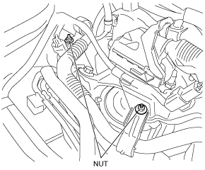
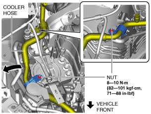
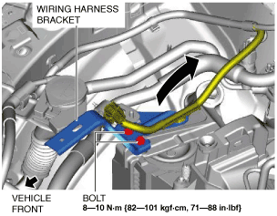
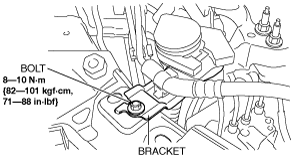
3. For SKYACTIV-D 1.5, perform the following procedure:
am3zzw00017735
|
am3zzw00017736
|
am3zzw00017236
|
am3zzw00017737
|
am3zzw00017738
|
4. Remove the bracket.
am3zzw00017739
|
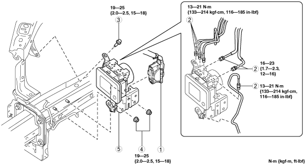
5. Remove in the order indicated in the table.
6. Install in the reverse order of removal.
7. After installation, add brake fluid, bleed the air, and inspect for fluid leakage. (See BRAKE FLUID AIR BLEEDING.)
8. Perform the following procedure to implement the DSC HU/CM automatic configuration.
9. Perform the DSC related parts sensor initialization procedure (only when replacing it with a new one). (See DSC RELATED PARTS SENSOR INITIALIZATION PROCEDURE.)
10. Perform the TPMS initialization procedure. (Vehicles with TPMS) (See TIRE PRESSURE MONITORING SYSTEM INITIALIZATION PROCEDURE.)
11. Clear the DTCs from the memory. (See ON-BOARD DIAGNOSIS [DYNAMIC STABILITY CONTROL (DSC)].)
am3zzw00015894
|
|
1
|
Connector
(See Connector Removal Note.)
(See Connector Installation Note.)
|
|
2
|
Brake pipe
(See Brake Pipe Removal Note.)
(See Brake Pipe Installation Note.)
|
|
3
|
Bolt
|
|
4
|
Nut
|
|
5
|
DSC HU/CM component
|
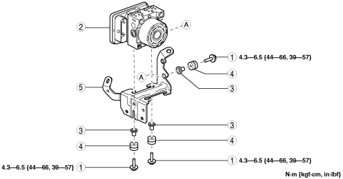
am3uuw00010905
|
|
1
|
Bolt
|
|
2
|
DSC HU/CM
|
|
3
|
Mount bolt
|
|
4
|
Mount rubber
|
|
5
|
Bracket
|
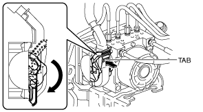
Connector Removal Note
1. Pull the lock lever down in the direction of the arrow while pressing the tab of the connector cover.
am3uuw00010906
|
2. Pull the connector toward the vehicle rear and remove it.
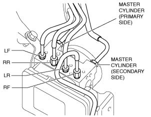
Brake Pipe Removal Note
1. Place an alignment marks on the brake pipe and DSC HU/CM.
am3uuw00010907
|
2. Apply protective tape to the connector to prevent brake fluid from entering.
3. Disconnect the brake pipes.
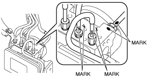
Brake Pipe Installation Note
1. Align the marks made before removal and install the brake pipe to the DSC HU/CM and brake pipe joint referring to the figure.
am3uuw00010908
|
2. Tighten the brake pipe to the specified torque using the commercially available flare nut wrench.
Connector Installation Note
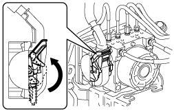
1. Connect the connector and pull the lock lever up in the direction of the arrow.
am3uuw00010909
|
2. After connecting the connector, verify that the connector cover is completely pushed in.
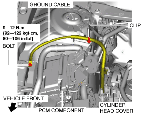
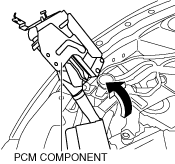
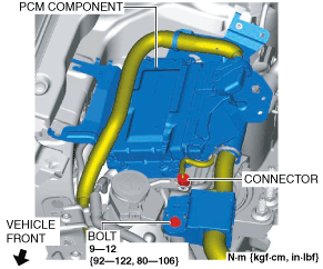
PCM Component Installation Note
1. Return the PCM component that was set aside to its original position.
2. Install the wiring harness protector and connector.
am3zzw00017253
|
3. Temporarily tighten the bolt shown in the figure.
am3zzw00017254
|
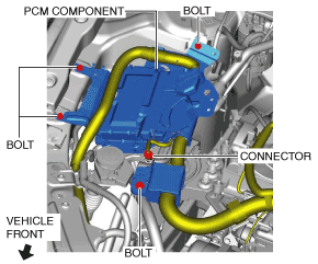
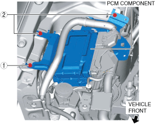
4. Tighten the PCM component installation bolts in the order shown in the figure.
am3zzw00017255
|